
Liquid discharging apparatus

Active Publication Date: 2017-07-20
BROTHER KOGYO KK
View PDF2 Cites 0 Cited by
  • Summary
  • Abstract
  • Description
  • Claims
  • Application Information

AI Technical Summary

Benefits of technology

The patent describes a system for controlling the liquid jet head in an inkjet printer. The system includes a suction pump and a tube pump for sucking ink from the cap. However, when the suction pump is used to press the tube, the load on the pump increases. To address this problem, the system includes a flushing process where the liquid is jetted from the nozzles simultaneously with the discharge process. By controlling the amount of liquid jetted, the system can reduce the current required to drive the pump and inhibit the current from increasing to an instant maximum. This results in a more efficient and controlled system.

Problems solved by technology

However, when the air suction process is carried out after the flushing process, then the entire maintenance time becomes long such that a long time is needed for proceeding to desired processes such as printing and the like.
Therefore, the instant maximum current value of the entire system is largely estimated, and hence there is such an adverse effect that an expensive power source is needed.

Method used


Image

  • Liquid discharging apparatus
  • Liquid discharging apparatus
  • Liquid discharging apparatus

Examples


Embodiment Construction

[0031]Referring to the accompanying drawings, an embodiment of the present teaching will be explained below.

[0032]

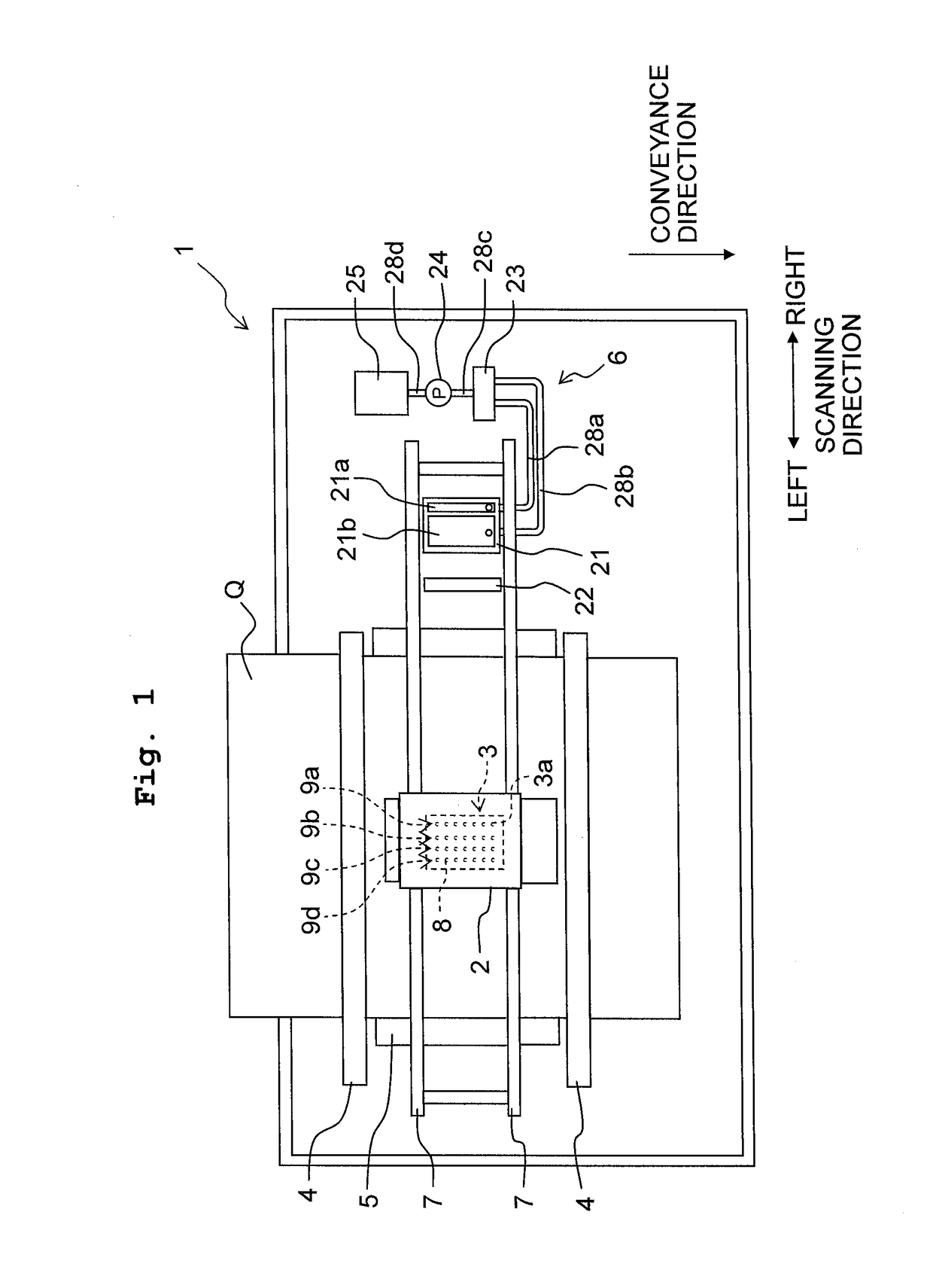
[0033]FIG. 1 is a schematic configuration diagram of a printer 1 according to the embodiment of the present teaching. As depicted in FIG. 1, the printer 1 according to this embodiment includes a carriage 2, an ink jet head 3, conveyance rollers 4, a platen 5, a maintenance unit 6, and the like.

[0034]The carriage 2 is supported by a pair of guide rails 7 extending in a scanning direction, to be movable in the scanning direction. The carriage 2 is connected with a carriage motor 41 (see FIG. 3) via an unshown belt or pulley and driven by the carriage motor 41 to move reciprocatingly in the scanning direction. Further, the following explanation will be made with definition of the right side and the left side in the scanning direction as depicted in FIG. 1. Further, in FIG. 1, the perpendicular direction to the page corresponds to the vertical or up-down direction, while the...


PUM


Abstract

There is provided a liquid discharging apparatus including: a liquid jet head, a receiving portion, a tube pump, and a controller. The controller carries out a process of acquiring present positional information of a pressing body inside the tube pump and a simultaneous process which simultaneously performs a flushing process and a discharge process and, as the flushing process, carries out a process of selectively performing either an ordinary flushing process or a restrained flushing process. In the simultaneous process, the controller carries out either the ordinary flushing process when the pressing body is not positioned to press an overlapped portion of a tube or the restrained flushing process when the pressing body is positioned to press the overlapped portion of the tube.

Description

CROSS REFERENCE TO RELATED APPLICATION[0001]The present application claims priority from Japanese Patent Application No. 2016-007550, filed on Jan. 19, 2016, the disclosure of which is incorporated herein by reference in its entirety.FIELD OF THE INVENTION[0002]The present invention relates to liquid discharging apparatuses discharging liquid from nozzles.DESCRIPTION OF THE RELATED ART[0003]Conventionally, there are known liquid discharging apparatuses capable of carrying out a flushing process to discharge liquid thickened in nozzles by jetting the liquid from the nozzles toward a cap, and an air suction process to suck the liquid in the cap with a suction pump so as to discharge the liquid accumulated in the cap due to the flushing process. However, when the air suction process is carried out after the flushing process, then the entire maintenance time becomes long such that a long time is needed for proceeding to desired processes such as printing and the like. Therefore, it has ...

Claims


Application Information

Patent Timeline
IPC IPC(8): B41J2/165
CPCB41J2/16505B41J2/1652B41J2/16508B41J2/16517B41J2/16523B41J2/16526B41J2002/16573
Inventor IIDA, SHOTAROUEDA, TOSHIRO
Owner BROTHER KOGYO KK
Features
  • Generate Ideas
  • Intellectual Property
  • Life Sciences
  • Materials
  • Tech Scout
  • Unparalleled Data Quality
  • Higher Quality Content
  • 60% Fewer Hallucinations
Learn More