
Assist Compensation For Actively Controlled Power Steering Systems

a technology of power steering and compensation, which is applied in the direction of electric steering, power steering steering, vehicle components, etc., can solve the problems of reducing the accuracy of driver torque input,

Active Publication Date: 2017-07-20
TRW AUTOMOTIVE US LLC
View PDF1 Cites 22 Cited by
  • Summary
  • Abstract
  • Description
  • Claims
  • Application Information

AI Technical Summary

Benefits of technology

The invention is a way to control the level of steering assist in an electric power steering system when there is a failure in the torque sensor. This is done by detecting when the front tires are starting to slip and using that information to adjust the steering assist level. This helps to prevent the driver from becoming uncomfortable or unable to steer the car effectively.

Problems solved by technology

In the rare case where the column torque sensor fails, there would be a sudden loss of the assistance provided by the motor, thus returning the system to a manual steering mode.
Modeling the gear compliance would typically require significant effort and face robustness challenges for accurate estimation of the driver torque input.
The accuracy of this approach, however, can be compromised significantly when road conditions deviate from those used to generate the tuning maps and look up tables.
Additionally, this methodology also does not typically take into account system non-linearity responses, such as gear friction.
Several challenges present themselves when implementing an angle based method, as described above.
First, additional upper column position sensors may not be available in all systems.
This may be due to a lack of available packaging space or costs issues associated with maintaining carry-over designs.
Second, relying on a single, angle sensor based approach can result in a self steer condition, particularly when the tuned assistance becomes greater than actual rack force.
Such a situation can occur as a result of overestimating the operating rack force, resulting in an over assist condition.
Third, when only a single sensor is used, bumps or pot holes generate transient impact force inputs that create control compensation issue.
The steering wheel will respond to rack forces imparted by the bump and the resulting angle causes an unintended assist.
Fourth, a vehicle driving in reverse also presents an issue when using angle based control.
Another issue arises when there is a quick / sudden reversal of steering direction relative to the initial direction of assist.
This condition, while generating a reduced counter torque, still opposes the desired steering motion, which affects driver reaction.
Furthermore, on low μ surfaces, the potential exists for the system / driver to over correct in a counter steer condition, making the vehicle harder to control.

Method used


Image

  • Assist Compensation For Actively Controlled Power Steering Systems
  • Assist Compensation For Actively Controlled Power Steering Systems
  • Assist Compensation For Actively Controlled Power Steering Systems

Examples


Embodiment Construction

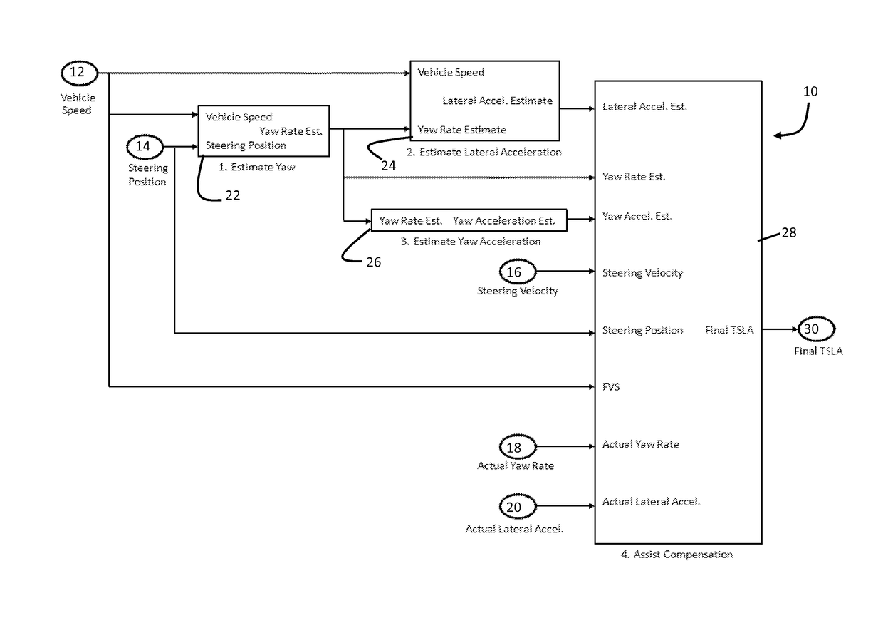
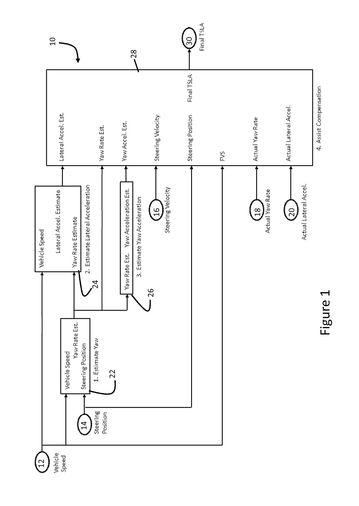
[0017]Referring now to the drawings, there is illustrated in FIG. 1 a schematic illustration of an EPS control system, shown generally at 10, having an algorithm configured to provide steering assist compensation with a limp-home mode feature. In a broad aspect of the invention, the algorithm is configured to determine a level of steering assistance based on one or more of the following input signals from the related sensors: Vehicle Speed 12, Steering Position 14, Steering Velocity 16, Actual Yaw Rate 18, and Actual Lateral Acceleration 20.

[0018]As shown in FIG. 1, a first functional block 22, identified as “Estimate Yaw,” calculates Yaw Rate based on Vehicle Speed (also termed “filtered vehicle speed, FVS”) and Steering position. A second functional block 24, identified as “Estimate Lateral Acceleration” calculates a Lateral Acceleration based on Vehicle Speed and the Estimated Yaw Rate from functional block 22. A third functional block 26, identified as “Estimate Yaw Acceleration...


PUM


Abstract

An electric power steering system includes a control for providing a calculated torque assist demand in the event of failure of a steering wheel torque sensor. The control is responsive to one or more of a vehicle speed, a steering column position, a steering column velocity, a gear lever position, a vehicle yaw rate and a vehicle lateral acceleration for generating the calculated torque assist demand. The control is operable to modify the torque assist demand by providing one or more of (a) friction and inertial compensation, (b) vehicle oversteer compensation, (c) reverse motion compensation, (d) damping compensation and (e) self steer prevention.

Description

CROSS-REFERENCE TO RELATED APPLICATIONS[0001]This application claims the benefit of United States Provisional Application No. 62 / 031,569, filed Jul. 31, 2014 and United States Provisional Application No. 62 / 031,580, filed Jul. 31, 2014, the disclosures of both applications are incorporated herein by reference.BACKGROUND OF THE INVENTION[0002]This invention relates in general to vehicular steering systems. In particular, this invention relates to control of vehicular electric power steering systems.[0003]EPS systems typically rely on a column torque sensor to measure the driver's steering command inputs and apply an assistance torque to the rack, via the motor, in order to support the driver in steering the vehicle. In the rare case where the column torque sensor fails, there would be a sudden loss of the assistance provided by the motor, thus returning the system to a manual steering mode. Previous angle-based, limp-home assist functions have addressed torque sensor failures in two ...

Claims


Application Information

Patent Timeline
IPC IPC(8): B62D5/04B62D6/00
CPCB62D5/0484B62D6/00B62D5/049B62D5/0463B62D5/0481B62D6/006
Inventor NAIK, ANANDSPIEKER, ARNOLDSWORN, TIM
Owner TRW AUTOMOTIVE US LLC
Learn More