
Display control method, display control device and display system

a control device and display technology, applied in the field of display technology, can solve the problems of affecting traffic safety and the inability of drivers to see the road, and achieve the effects of reducing the light reflectance of this region, and reducing the glare intensity of the surface of the polarizing pla

Active Publication Date: 2017-07-20
BOE TECH GRP CO LTD
View PDF27 Cites 7 Cited by
  • Summary
  • Abstract
  • Description
  • Claims
  • Application Information

AI Technical Summary

Benefits of technology

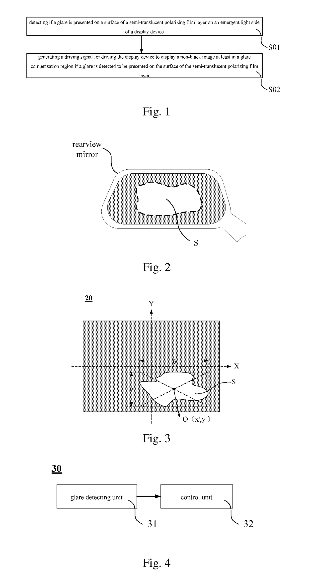
The present patent aims to provide a display control method, device and system to reduce glare intensity on a mirror surface, such as a rearview mirror, by increasing light transmittance and reducing light reflectance in the glare region. This helps to weaken the mirror effect of glare and reduce the glare intensity on the surface of the polarizing plate, which can enhance traffic safety and provide a better driving experience.

Problems solved by technology

However, in some cases, for example, when the vehicle is traveling under strong sunshine or when the vehicle is driving at night and a vehicle following it turns on strong light such as a high beam, an extremely strong light is reflected by the rearview mirror and a glare is created on a reflection film, resulting in that the driver cannot see the road, affecting traffic safety.

Method used


Image

  • Display control method, display control device and display system
  • Display control method, display control device and display system
  • Display control method, display control device and display system

Examples


Embodiment Construction

[0039]Exemplary embodiments of the present disclosure will be described hereinafter in detail with reference to the attached drawings, wherein the like reference numerals refer to the like elements. The present disclosure may, however, be embodied in many different forms and should not be construed as being limited to the embodiment set forth herein; rather, these embodiments are provided so that the present disclosure will be thorough and complete, and will fully convey the concept of the disclosure to those skilled in the art.

[0040]It is to be noted that, unless otherwise defined, all terms (including technical and scientific terms) used in the embodiments of the present disclosure have the same meanings as commonly understood by those skilled in the art. It should also be understood that terms such as those defined in the conventional dictionary should be interpreted as having a meaning that is consistent with their meaning in the context of the related art and should not be inte...


PUM


Abstract

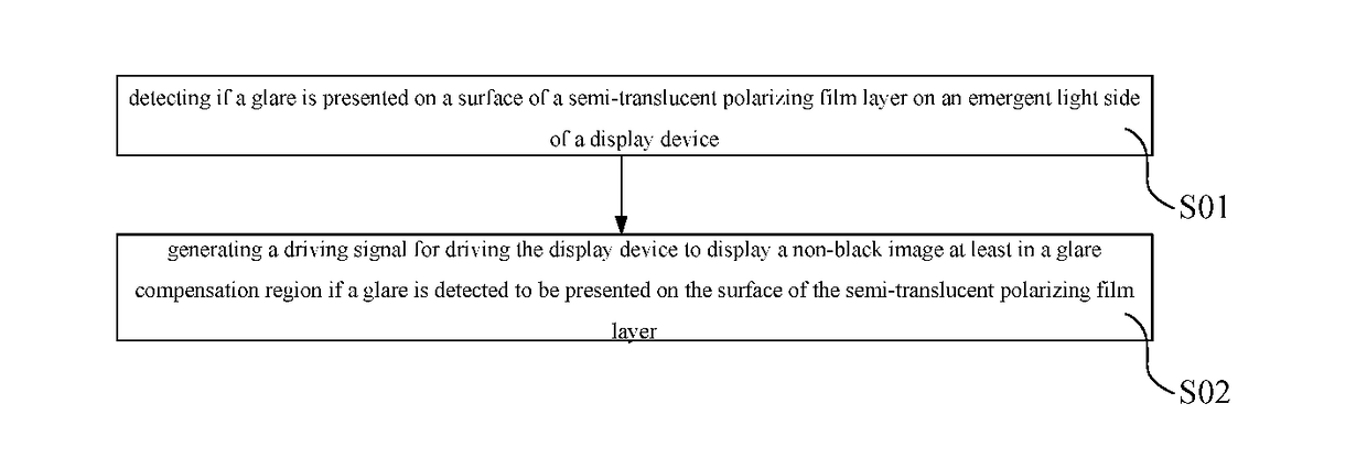
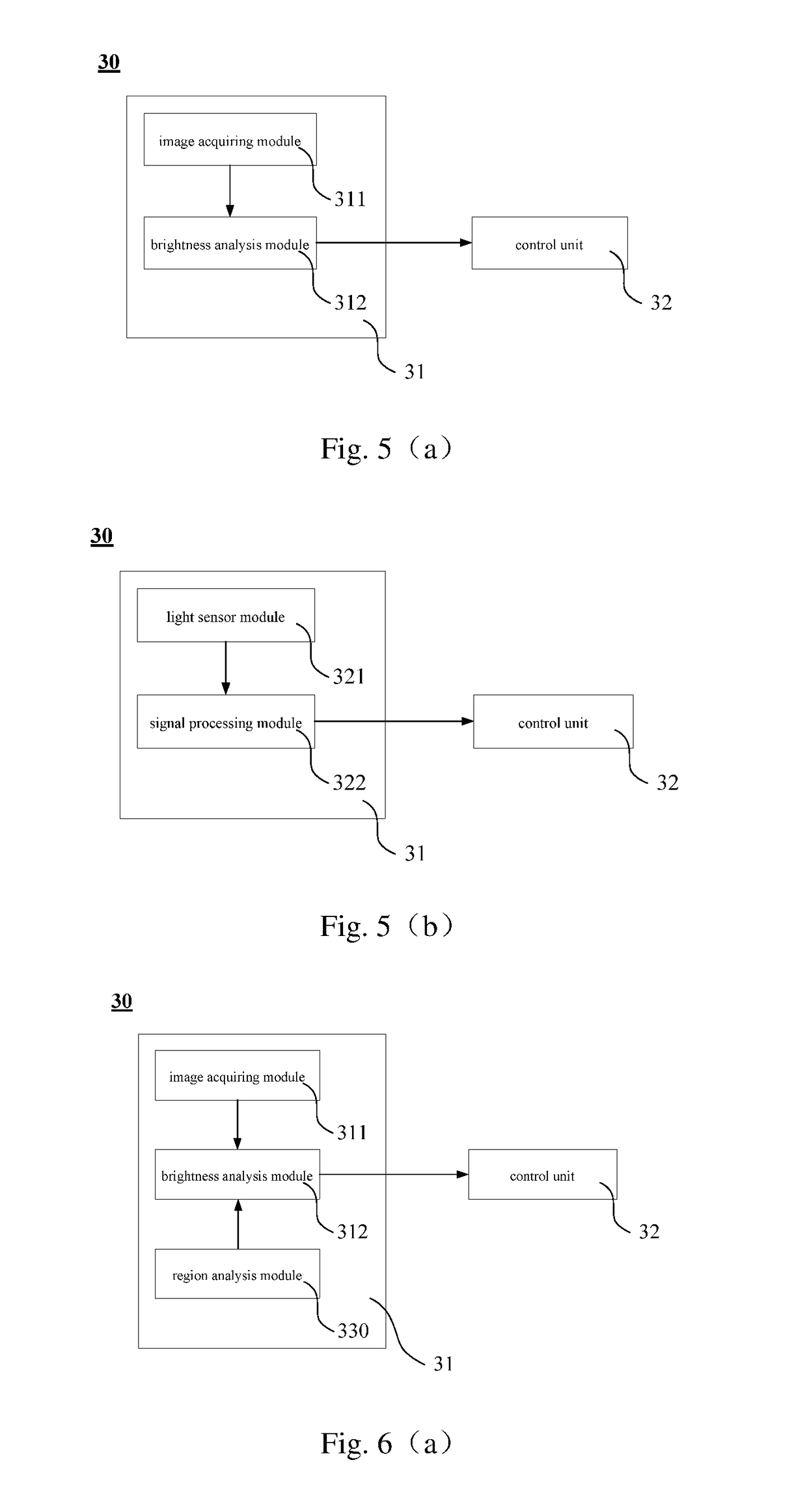
The embodiments of the present disclosure relate to the display technology field, and provide a display control method, a display control device and a display system. The display control method includes: detecting if a glare is presented on the surface of the semi-translucent polarizing film layer on the emergent light side of the display device; generating a driving signal for driving the display device to display a non-black image in a glare compensation region if a glare is detected to be presented on the surface of the semi-translucent polarizing film layer; in which the glare compensation region corresponds to a glare region in the semi-translucent polarizing film layer and the glare region is an region in which a glare is presented. The display control method of the present disclosure may reduce glare intensity when a glare is created on a mirror surface such as a rearview mirror.

Description

CROSS-REFERENCE TO RELATED APPLICATION[0001]This application claims the benefit of Chinese Patent Application No. 201510425436.x filed on Jul. 17, 2015 in the State Intellectual Property Office of China, the whole disclosure of which is incorporated herein by reference.BACKGROUND OF THE INVENTION[0002]Field of the Invention[0003]The present disclosure relates to display technology field, especially relates to a display control method, a display control device and a display system.[0004]Description of the Related Art[0005]The rearview mirror is one of essential accessories of the vehicle, which can clearly reflect situations of the rear, side and bottom of the vehicle, so that the driver can see these positions indirectly, and the driver's field of view can be expanded.[0006]A surface of the rearview mirror is provided with a reflective film, which serves as a mirror reflection. However, in some cases, for example, when the vehicle is traveling under strong sunshine or when the vehic...

Claims


Application Information

Patent Timeline
Patent Type & Authority Applications(United States)
IPC IPC(8): G09G5/10B60R1/12
CPCG09G5/10B60R1/12B60R2001/1253B60K2350/106B60K2350/2013G09G2380/10B60K2350/2069B60K2350/927G09G2320/0626G09G2360/144B60K2350/2078G02F1/1309G09G3/36B60R1/083G09G2300/0456B60K2360/21B60K35/415B60K2360/349B60K35/60B60K2360/777
Inventor WU, YANBING
Owner BOE TECH GRP CO LTD
Learn More