Modular energy storage direct converter system

a direct converter and module technology, applied in the field of electric engineering, can solve the problems of loss, damage to the cells, and inability to adapt the operating points of the system, and achieve the effect of increasing energy efficiency and saving battery cells

Active Publication Date: 2017-07-20
UNIVET DER BUNDESWEHR MUENCHEN
View PDF4 Cites 34 Cited by
  • Summary
  • Abstract
  • Description
  • Claims
  • Application Information

AI Technical Summary

Benefits of technology

[0051]The invention also relates to an electric drive for a vehicle, which comprises a modular energy storage direct converter system according to any of the previously described embodiments. As mentioned above, for this case no additional converter is required for the operation of the engine, nor any charging converter. In addition, in particular in the case of electric vehicle applications, the advantages of the system, namely an increased energy efficiency, conservation of the battery cells and the facility that the deterioration of individual cells has no influence on the performance of the other cells in the assembly, are of particular benefit.

Problems solved by technology

However, such known battery management systems are comparatively expensive, lossy, usually expensive and under certain circumstances even damaging to the cells.
One disadvantage is that the operating points of the system either cannot be adapted to the current requirements at all, or only to a small extent, and that the overall power of the system is typically limited by the weakest sub-unit in the assembly.
This charge transfer, however, is always accompanied by an energy loss and also reduces the service life of the cells.
In addition, current systems typically operate with high technical circuitry and filter complexity, which increases the energy consumption and the costs.
Similar problems to those in battery systems also occur in energy conversion systems, which comprise, for example, fuel cells or solar modules as the energy conversion elements.

Method used


Image

  • Modular energy storage direct converter system
  • Modular energy storage direct converter system
  • Modular energy storage direct converter system

Examples


Embodiment Construction

[0066]For a better understanding of the present invention, reference is made hereafter to the preferred exemplary embodiment shown in the drawings, which is described by reference to specific terminology. It should however be noted that this is not intended to limit the scope of protection of the invention, since such changes and further modifications to the device and the method, together with such other applications of the invention as are shown therein, are regarded as present or future knowledge of the person skilled in the art.

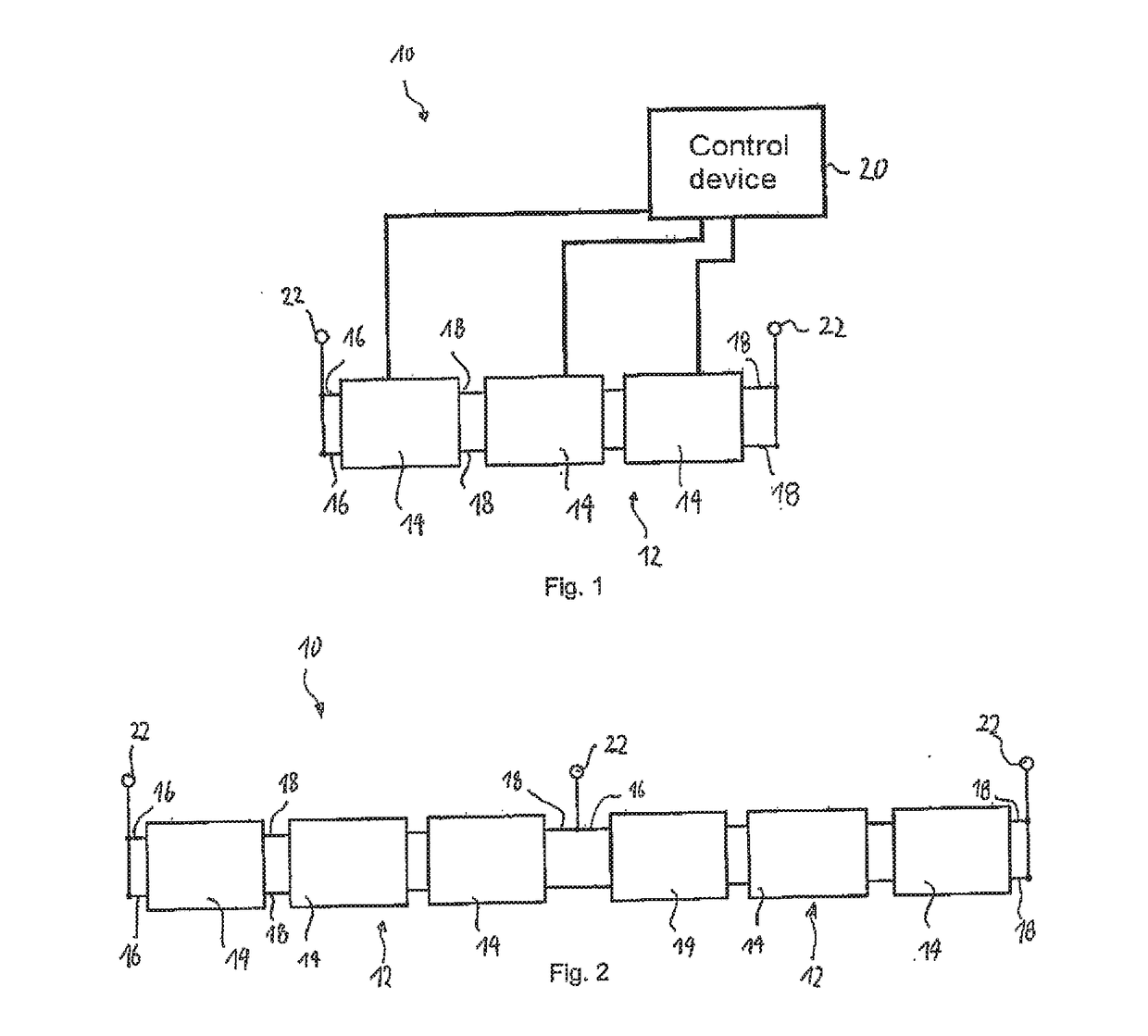
[0067]FIG. 1 shows an exemplary embodiment of a modular energy storage direct converter system 10 according to one embodiment of the invention. The system 10 comprises a bridge branch 12, which comprises a plurality of modules 14 connected one after the other. For the sake of simplicity, in FIG. 1 only three series-connected modules 14 are shown, it is understood however that the number of modules 14 in a bridge branch 12 in practical applications will be...


PUM


Abstract

invention describes a modular energy storage direct converter system (10) which comprises the following: a control device (20) and at least one bridge branch (12) which comprises The a plurality of modules (14) which are connected in series, wherein each of said modules (14) comprises a storage element for electrical energy, in particular a battery, or an energy conversion element. Said modules (14) are designed and can be actuated such that the storage element or energy conversion element of a module can be selectively deactivated, and that the storage elements or energy conversion elements of two modules, which are separated by at least one intermediate module with a deactivated storage element/energy conversion element, can be connected selectively in parallel and in series.

Description

FIELD OF THE INVENTION[0001]The present invention is in the field of electrical engineering. In particular it relates to a modular energy storage direct converter system that contains at least one bridge branch, which comprises a plurality of modules connected one after the other.BACKGROUND OF THE INVENTION[0002]Battery systems are gaining increased importance in many areas of technology. A particularly important application relates to electric vehicles, in which the battery systems are a key component for the mobility of the future. A further application of extraordinary importance is that of battery systems as stationary energy storage devices for renewable energies.[0003]Many of the energy storage systems currently in use consist of a series connection or parallel connection of up to thousands of energy storage elements, wherein a relatively small voltage in comparison to the required total voltage is applied, or can be applied to each energy storage element. By using a series co...

Claims


Application Information

Patent Timeline
Patent Type & Authority Applications(United States)
IPC IPC(8): H02J3/38H02J7/00
CPCH02J3/382H02J3/383H02J2007/0059H02J7/0068H02J7/0052H02J3/387H02M7/483Y02E10/56H02M1/325H02M7/4835H02M7/4837H02M1/0095H02J7/00H02J2207/20H02J3/38H02J3/388
Inventor HELLING, FLORIANWEYH, THOMAS
Owner UNIVET DER BUNDESWEHR MUENCHEN
Why Eureka
Try Eureka