Wheel driving device and cleaner robot having the same

a technology of driving device and cleaner robot, which is applied in the direction of carpet cleaners, instruments, cleaning machines, etc., can solve the problems of reducing the cleaning efficiency increasing the power consumption of the cleaner robot, and affecting the operating time of the cleaner robot, so as to achieve the effect of reducing the power consumption of the wheel driving devi

Active Publication Date: 2017-07-27
NIPPON DENSAN CORP
View PDF4 Cites 7 Cited by
  • Summary
  • Abstract
  • Description
  • Claims
  • Application Information

AI Technical Summary

Benefits of technology

[0008]According to the wheel driving device related to an exemplary embodiment of the

Problems solved by technology

Thus, the power consumption of the cleaner robot is increased.
In addition, since the cleaner robot is driven by batteries, the amount of the power consumption influences operating time of the cleaner robot.
Furthermore, if t

Method used


Image

  • Wheel driving device and cleaner robot having the same
  • Wheel driving device and cleaner robot having the same
  • Wheel driving device and cleaner robot having the same

Examples


first embodiment

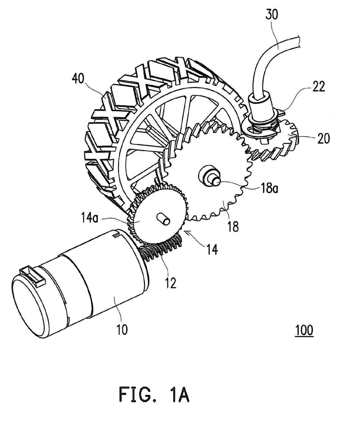
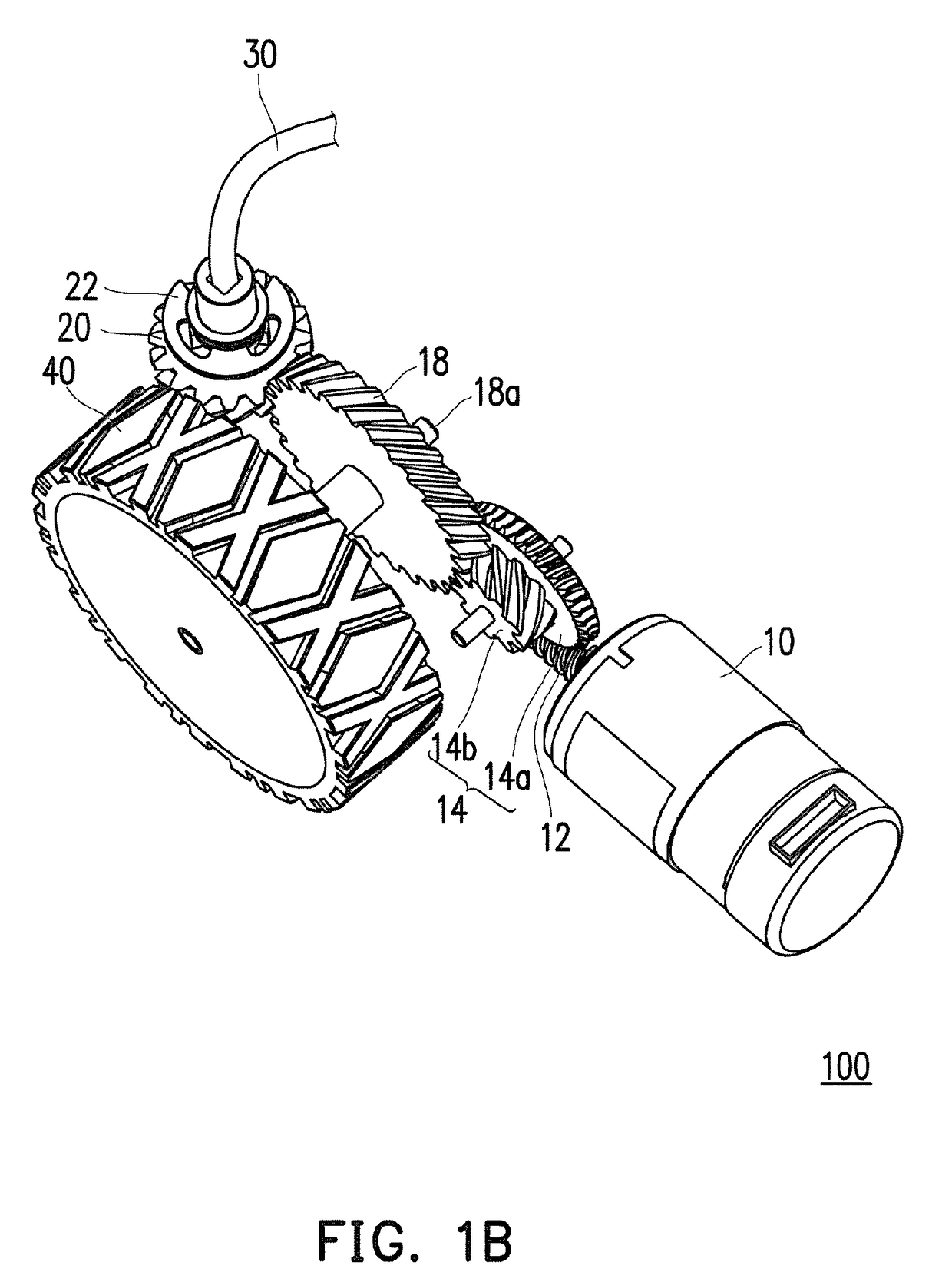
[0030]As shown in FIG. 1 A and FIG. 1B, the wheel driving device 100 of the first embodiment includes the motor 10, an input gear 12, at least one transmission gear 14, a final gear 18, an extraction gear 20 and a power transmission part 30. In the wheel driving device 100, the motor 10 is mainly for providing power. By outputting the power through the motor 10 to rotate a shaft 10a of the motor 10, the gear set at the rear is driven. That is, the motor 10 rotates the shaft 10a. In the present embodiment, a brush motor, for example, may be employed as the motor 10.

[0031]The input gear 12 is fixed to the shaft 10a of the motor 10. The input gear 12 is, for example, a worm gear, and the worm gear is rotated through rotation of the shaft 10a. The wheel driving device 100 further includes at least one transmission gear 14, wherein the transmission gear 14 is rotated by rotation of the won't gear, and the power of the motor 10 is transmitted to the final gear 18 on the rear side. That is...

second embodiment

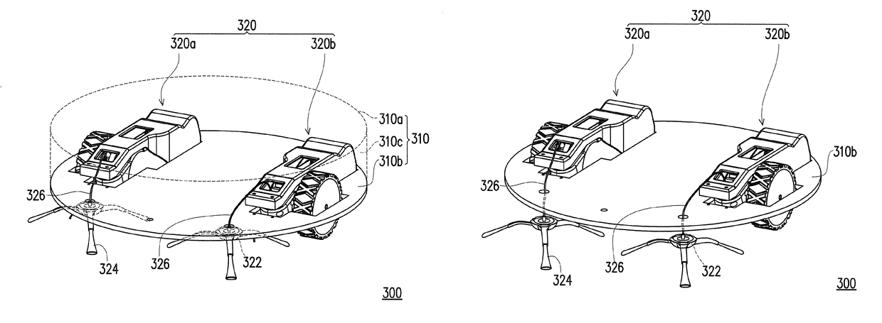
[0046]In addition, the side brush of a conventional cleaner robot must be driven by another motor, and an arrangement position of the side brush is therefore limited. However, in the present embodiment, the motor of the wheel driving devices 320a and 320b simultaneously drives the wheel and the cleaner heads 322 and 324, and a flexible power transmission part (the power transmission part 30 in FIG. 1A, FIG. 1B and so on) is used for transmission of power to the cleaner heads 322 and 324. Therefore, design flexibility for the cleaner robot 300 can be further increased. That is, by the structure of the present embodiment, the side brush can be more flexibly arranged. FIG. 9A, FIG. 9B and FIG. 9C are schematic views showing arrangement positions of the cleaner heads 322 and 324 in the As shown in FIG. 9A, the side brush is arranged on the base 310b outside the housing 310. Accordingly, the side brush can be arranged in a place not occupying internal space of the housing. Since the pow...


PUM


Abstract

A wheel driving device includes: a motor rotating a shaft: an input gear fixed to the shaft; at least one transmission gear meshed with the input gear to transmit power of the motor; and a final gear meshed with the transmission gear and connected with a wheel via an axis to transmit the power from the transmission gear to the wheel. The wheel driving device includes an extraction gear meshed with the final gear or the transmission gear, and a power transmission part connected with the extraction gear to transmit the power from the extraction gear to a cleaner head.

Description

CROSS-REFERENCE TO RELATED APPLICATION[0001]This application claims the priority benefit of Taiwan Application no. 105102298, filed on Jan. 26, 2016. The entirety of the above-mentioned patent application is hereby incorporated by reference herein and made a part of this specification.BACKGROUND OF THE INVENTION[0002]Field of the Invention[0003]The present invention relates to a wheel driving device and a cleaner robot having a wheel driving device.[0004]Description of the Related Art[0005]Among home appliances, self-propelled cleaners, or so-called cleaner robots, which automatically clean the floor, have become common equipment. For example, JP 2011-161242 discloses a conventional cleaner robot. In the cleaner robot described in JP 2011-161242, a plurality of motors are arranged, which are, respectively, one for driving a blower, two for driving a wheel driving device, one for driving a main brush, and one (or two) for driving a subbrush. In addition, the cleaner robot generally h...

Claims


Application Information

Patent Timeline
IPC IPC(8): A47L11/24F16C1/02B25J5/00B60K17/28B60K25/06B60K1/02F16H1/22B60K17/04
CPCA47L11/24F16H1/222F16C1/02B60K17/043B60K17/28G05D2201/0203B60K1/02B25J5/007F16H2057/02039F16H2057/02034B60K2025/005B60K25/06A47L9/009A47L9/0411A47L9/0427A47L9/0433A47L9/0438A47L9/0488A47L9/2847A47L9/2852A47L11/4066A47L11/4069A47L2201/00
Inventor LIU, CHUN-HSIENICHIZAKI, HIROYUKI
Owner NIPPON DENSAN CORP
Why Eureka
Try Eureka