Dust collection device
- Summary
- Abstract
- Description
- Claims
- Application Information
AI Technical Summary
Benefits of technology
Problems solved by technology
Method used
Image
Examples
first embodiment
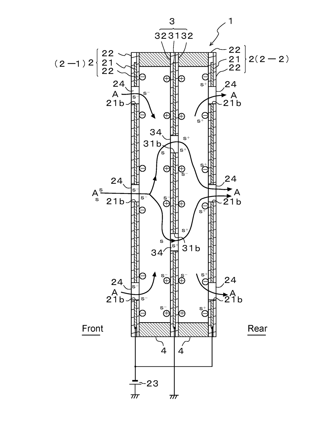
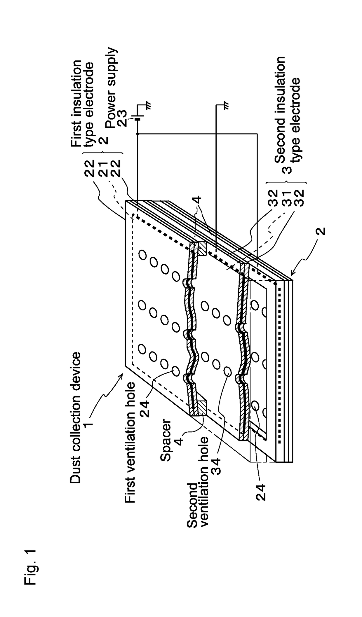
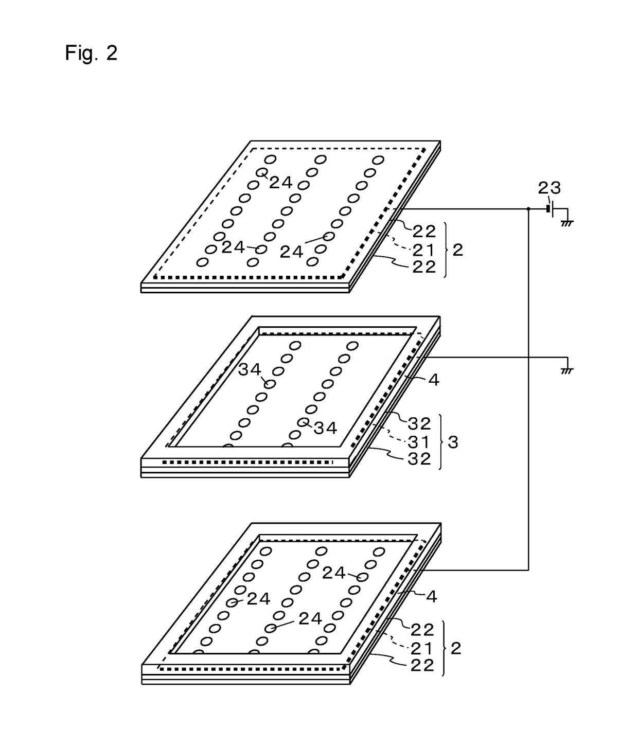
[0059]FIG. 1 is a partially cutaway perspective view of a dust collection device according to a first embodiment of the present invention. FIG. 2 is an exploded perspective view of the dust collection device according to the first embodiment. FIG. 3 is a sectional view of the dust collection device.
[0060]As shown in FIG. 1, the dust collection device 1 is structured by laminating first insulation type electrodes 2 and a second insulation type electrode 3 alternately via insulating spacers 4.
[0061]Specifically, in this embodiment, as shown in FIG. 2, two first insulation type electrodes 2 and one second insulation type electrode 3 are laminated alternately. In this case, by interposing a spacer 4 having a quadrilateral frame shape between the second insulation type electrode 3 and the upper first insulation type electrode 2, and interposing a similar spacer 4 between the second insulation type electrode 3 and the lower first insulation type electrode 2, a space corresponding to a thi...
second embodiment
[0093]Next, a second embodiment of the present invention is described.
[0094]FIG. 8 is a sectional view showing a dust collection device according to a second embodiment of the present invention. FIG. 9 are plan views of insulation type electrodes, FIG. 9(a) shows a first insulation type electrode 2, and FIG. 9(b) shows a second insulation type electrode 3. FIG. 10 is a partial enlarged view of the first and second ventilation holes 24 and 34.
[0095]As shown in FIG. 8, in the dust collection device 1 of this embodiment, structures of the first and second ventilation holes 24 and 34 of the first and second insulation type electrodes 2 and 3 are different from those of the first embodiment.
[0096]Specifically, in the first ventilation hole 24 of each first insulation type electrode 2, a bore diameter of the hole 22a′ of the upper first insulating layer 22 in the drawing is set to be larger than a bore diameter of the hole 21a of the first electrode 21 and a bore diameter of the hole 22a ...
third embodiment
[0103]Next, a third embodiment of the present invention is described.
[0104]FIG. 11 is a sectional view showing a dust collection device according to a third embodiment of the present invention. FIG. 12 are plan views of insulation type electrodes, FIG. 12(a) shows a first insulation type electrode 2 and FIG. 12(b) shows a second insulation type electrode 3. FIG. 13 is a partial enlarged view of first and second ventilation holes 24 and 34.
[0105]As shown in FIG. 11, in the dust collection device 1 of this embodiment, structures of the first and second electrodes 21 and 31 exposed inside the first and second ventilation holes 24 and 34 of the first and second insulation type electrodes 2 and 3 are different from those in the first and second embodiments described above.
[0106]Specifically, a part of the first electrode 21 is exposed inside the first ventilation hole 24 of the first insulation type electrode 2, and this exposed portion 21d is formed of conductive fibers directed toward ...
PUM
 Abstract
Description
Claims
Application Information
 - R&D
- Intellectual Property
- Life Sciences
- Materials
- Tech Scout
- Unparalleled Data Quality
- Higher Quality Content
- 60% Fewer Hallucinations
Browse by: Latest US Patents, China's latest patents, Technical Efficacy Thesaurus, Application Domain, Technology Topic, Popular Technical Reports.
© 2025 PatSnap. All rights reserved.Legal|Privacy policy|Modern Slavery Act Transparency Statement|Sitemap|About US| Contact US: help@patsnap.com


