

Particulate sensor and particulate detection system
- Summary
- Abstract
- Description
- Claims
- Application Information
AI Technical Summary
Benefits of technology
Problems solved by technology
Method used
Image

Examples
embodiment
[0088]An embodiment of the present invention will be described with reference to the drawings. However, the present invention should not be construed as being limited thereto.
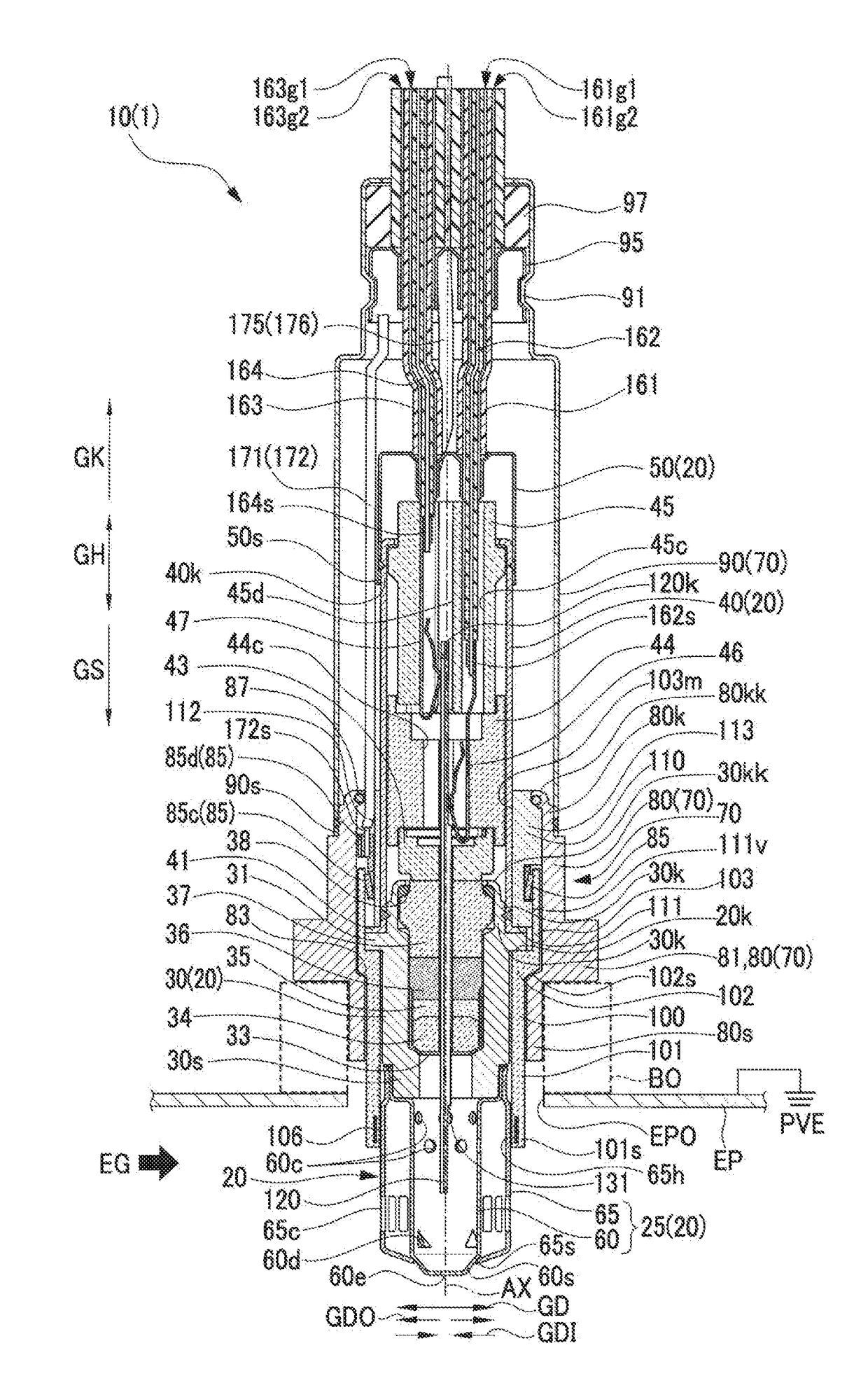
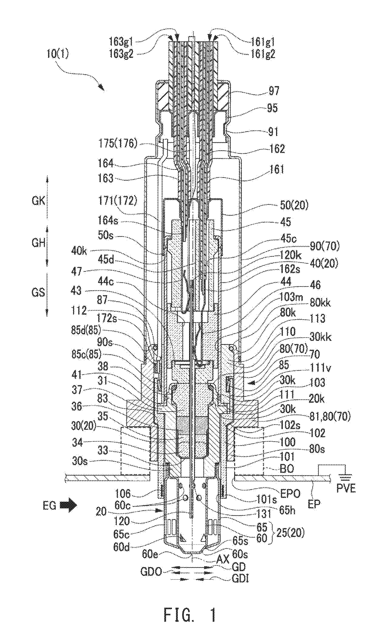
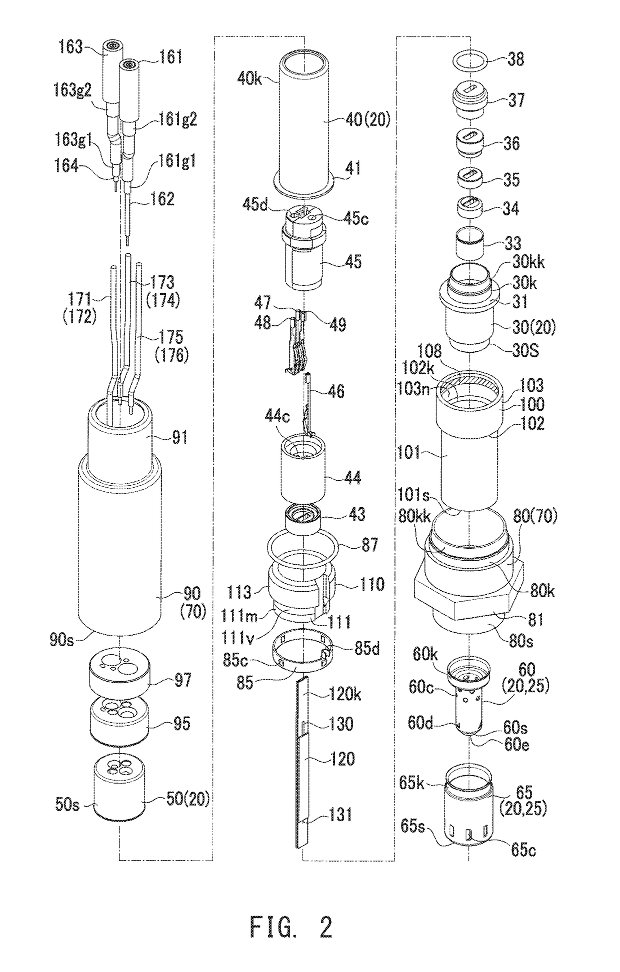
[0089]FIGS. 1 and 2 show a main portion of a particulate sensor 10 according to the present embodiment which is a part of a particulate detection system 1. FIGS. 3A and 3B show a first insulating spacer (heater member) 100 used in the particulate sensor 10. FIGS. 4 and 5 show a ceramic element. FIG. 6 shows a circuit section 200 of the particulate detection system 1. In FIG. 1, in a longitudinal direction GH along an axial line AX of the particulate sensor 10, a side (lower side in the drawing) on which a gas introduction pipe 25 is disposed corresponds to a distal end side GS, and a side (upper side in the drawing) on which electric wires 161, 163, etc., extend corresponds to a proximal end side GK.
[0090]The particulate detection system 1 detects the amount of particulates S (soot, etc.) contained in exhaust g...
first modification
(First Modification)
[0141]Next, a first modification of the above-described embodiment will be described with reference to FIG. 8. In the above-described embodiment, the particulate sensor 10 used for the particulate detection system 1 has a structure in which the contact portion 101s of the distal end portion 101 of the first insulating spacer 100 comes into contact with the outer tube to-be-contacted portion 65h of the outer protector 65 of the gas introduction pipe 25. Therefore, in the particulate sensor 10 of the embodiment, as result of supply of electric current to the heater wiring 105 (the heat generation resistor 106), the outer protector 65 is heated through the outer tube to-be-contacted portion 65h, whereby the adhering particulates SF which have accumulated on the inner circumferential surface of the outer tube to-be-contacted portion 65h of the outer protector 65 and the vicinity thereof can be removed.
[0142]In contrast, a particulate sensor 310 (see FIG. 8) used for ...
second modification
(Second Modification)
[0149]Next, a second modification of the above-described embodiment will be described with reference to FIG. 9. In the particulate sensor 310 (FIG. 8) used for the particulate detection system 301 of the first modification, the outer protector 365 and the inner protector 360 are heated from the outer side by supplying electric current to the heat generation resistor 106. Specifically, the contact portion 101s of the distal end portion 101 of the first insulating spacer (the heater member) 100 is brought into contact with the outer tube to-be-contacted portion 365h of the outer protector 365 from the outer side. Further, the overlapping to-be-contacted portion 360h of the inner protector 360 is caused to overlap with the outer tube to-be-contacted portion 365h, so that the contact portion 101s of the first insulating spacer (the heater member) 100 comes into indirect contact with the overlapping to-be-contacted portion 360h of the inner protector 360.
[0150]In con...
PUM
 Abstract
Description
Claims
Application Information