Hybrid Propulsion System

a propulsion system and hybrid technology, applied in the direction of efficient propulsion technologies, machines/engines, electrochemical generators, etc., can solve the problems of increasing the required amount of work, affecting the efficiency of the compressor section, and introducing lubrication difficulties, so as to improve the efficiency of the gas turbine engine

Active Publication Date: 2017-07-27
GENERAL ELECTRIC CO
View PDF31 Cites 31 Cited by
  • Summary
  • Abstract
  • Description
  • Claims
  • Application Information

AI Technical Summary

Benefits of technology

[0006]In one exemplary embodiment of the present disclosure a gas turbine engine is provided. The gas turbine engine includes a core turbine engine, a fan mechanically coupled to the core turbine engine, and an electric motor mechanically coupled to at least one of the core turbine engine and the fan. The gas turbine engine also includes a fuel cell for providing electrical energy to the electric motor, the fuel cell generating water as a byproduct, the gas turbine engine directing the water generated by the fuel cell to the core turbine engine during operation of the gas turbine engine to improve an efficiency of the gas turbine engine.
[0007]In another exemplary embodiment of the present disclosure, an aeronautical propulsion system including a turbine engine is provided. The aeronautical propulsion system includes a fan, an electric motor drivingly coupled to the fan, and a fuel cell. The fuel cell provides electrical energy to the electric motor and generates water as a byproduct. The aeronautical propulsion system directs the water generated by the fuel cell to the turbine engine during operation of the aeronautical propulsion system to improve an efficiency of the aeronautical propulsion system.

Problems solved by technology

If the temperature of the air reaches a certain threshold temperature during the compression process, the high temperature air may, e.g., interfere with reliable action of the compressor section and introduce lubrication difficulties, in addition to increasing a required amount of work to compress the air to a given pressure.
Such may have a detrimental effect on an efficiency of the compressor section.
As a consequence, the compressor section of certain gas turbine engines are not operated to their full potential.

Method used


Image

  • Hybrid Propulsion System
  • Hybrid Propulsion System
  • Hybrid Propulsion System

Examples


Embodiment Construction

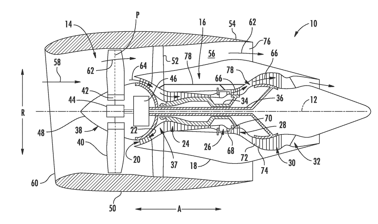
[0016]Reference will now be made in detail to present embodiments of the invention, one or more examples of which are illustrated in the accompanying drawings. The detailed description uses numerical and letter designations to refer to features in the drawings. Like or similar designations in the drawings and description have been used to refer to like or similar parts of the invention. As used herein, the terms “first”, “second”, and “third” may be used interchangeably to distinguish one component from another and are not intended to signify location or importance of the individual components. The terms “upstream” and “downstream” refer to the relative direction with respect to fluid flow in a fluid pathway. For example, “upstream” refers to the direction from which the fluid flows, and “downstream” refers to the direction to which the fluid flows.

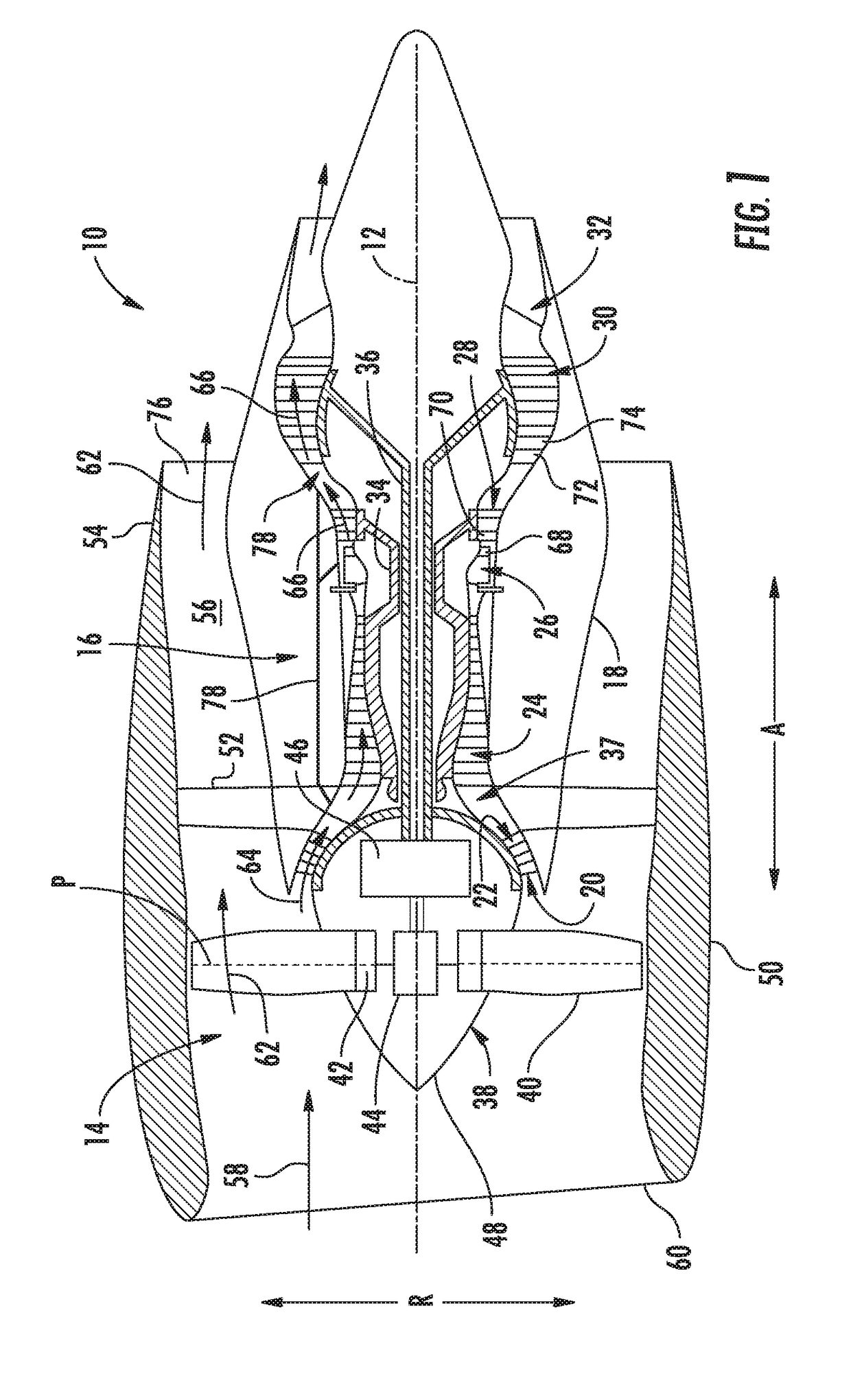
[0017]Referring now to the drawings, wherein identical numerals indicate the same elements throughout the figures, FIG. 1 is a schematic...


PUM

PropertyMeasurementUnit
electrical energyaaaaaaaaaa
mechanical poweraaaaaaaaaa
combustion gasesaaaaaaaaaa

Abstract

An aeronautical propulsion system including a turbine engine having a fan and an electric motor drivingly coupled to at least one of the fan or the turbine engine. The aeronautical propulsion system additionally includes a fuel cell for providing electrical energy to the electric motor, the fuel cell generating water as a byproduct. The aeronautical portion system directs the water generated by the fuel cell to the turbine engine during operation to improve an efficiency of the aeronautical propulsion system.

Description

FIELD OF THE INVENTION[0001]The present subject matter relates generally to a hybrid aeronautical propulsion system.BACKGROUND OF THE INVENTION[0002]A gas turbine engine generally includes a fan and a core arranged in flow communication with one another. The core of the gas turbine engine generally includes, in serial flow order, a compressor section, a combustion section, a turbine section, and an exhaust section. In operation, at least a portion of air over the fan is provided to an inlet of the core. Such portion of the air is progressively compressed by the compressor section until it reaches the combustion section. Fuel is mixed with the compressed air and burned within the combustion section to provide combustion gases. The combustion gases are routed from the combustion section through the turbine section to drive one or more turbines within the turbine section. The one or more turbines within the turbine section may be coupled to one or more compressors of the compressor sec...

Claims


Application Information

Patent Timeline
Patent Type & Authority Applications(United States)
IPC IPC(8): F02C3/30F02C7/00H01M8/04291B64D27/24H01M8/06F02C6/20B64D27/18
CPCF02C3/305F02C6/206F02C7/00B64D27/18B64D27/24H01M2250/10H01M8/04291B64D2041/005B64D2027/026H01M2250/20H01M8/06F02C7/16F02C7/12F02C6/00F02C7/36F02K3/06F05D2260/40311H01M8/0618H01M8/00Y02T50/60
Inventor SENNOUN, MOHAMMED EL HACIN
Owner GENERAL ELECTRIC CO
Why Eureka
Try Eureka