Progressive vortex pump

a vortex pump and progressive technology, applied in the direction of non-positive displacement pumps, liquid fuel engines, fluid removal, etc., can solve the problems of rubbing of the rotor, and achieve the effect of removing the problem of excessive axial load

Active Publication Date: 2017-07-27
HIGRA IND
View PDF4 Cites 2 Cited by
  • Summary
  • Abstract
  • Description
  • Claims
  • Application Information

AI Technical Summary

Benefits of technology

[0013]The goal of the invention is to provide a progressive vortex...

Problems solved by technology

Since the fluid pressure increases along the pumping direction, the pressure of the posterior fluid film becomes larger than the pressure of the anteri...

Method used


Image

  • Progressive vortex pump
  • Progressive vortex pump
  • Progressive vortex pump

Examples


Embodiment Construction

[0028]The following preferred embodiments are provided for further illustrating, but not for limiting, the present invention.

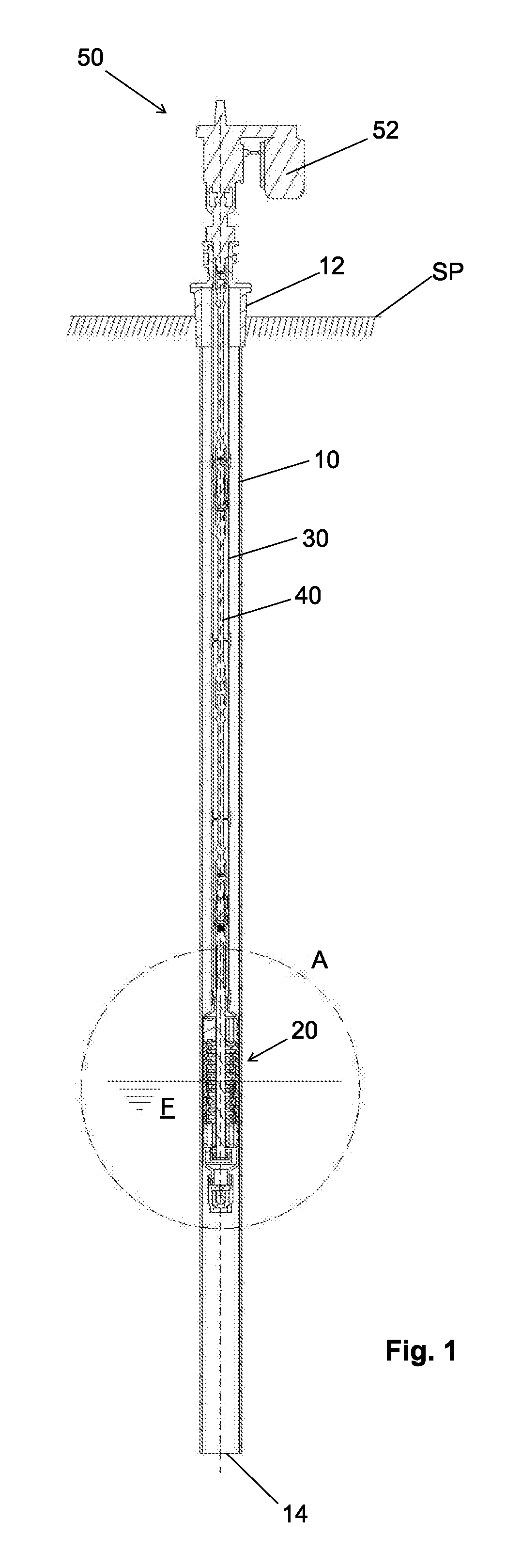
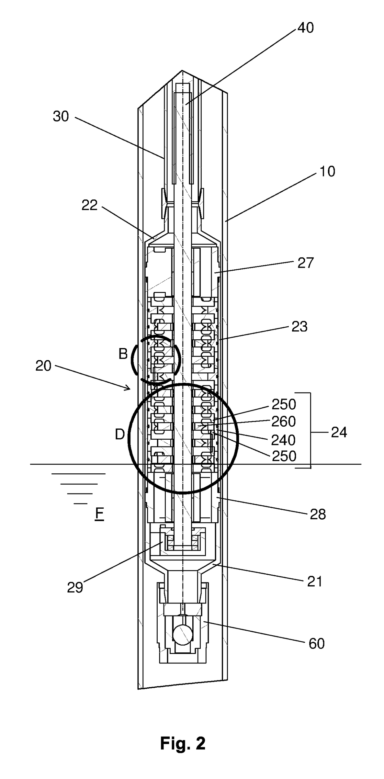
[0029]The invention provides a progressive vortex pump comprising an inlet housing (21) in contact with the fluid (F) to be pumped, a pump housing (23) connected to the inlet housing (21) and an outlet housing (22) connected to the pump housing (23) and connected to a pumping pipe (30).

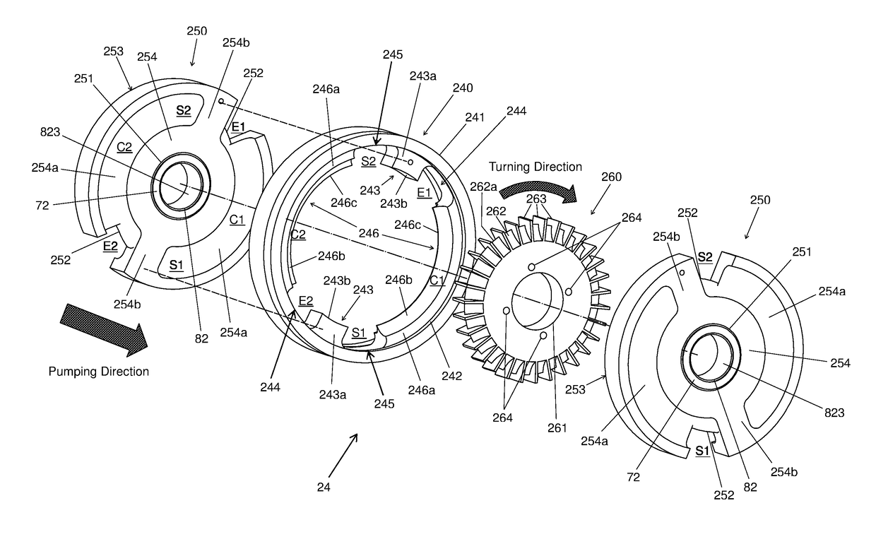
[0030]The pump housing (23) comprises multiple adjacent pumping stages (24), each pump stage (24) having a stator (240) with an anterior side and a posterior side, said stator (240) being attached within the pump housing (23); a first diffuser (250) coupled to the anterior side of the stator (240); a second diffuser (250) coupled to the posterior side of the stator (240); and a disc-shaped rotor (260) with a central bore (261) and a rim (262) with vanes (263). The rotor (260) is positioned within the stator (240), between the first diffuser (250) and the second diffuser (250). T...


PUM


Abstract

A progressive vortex pump comprises an inlet housing in contact with the pumped fluid, a pump housing connected to the inlet housing, and an outlet housing connected to the pump housing and connected to a pumping pipe. The pump housing comprises a disc-shaped rotor having a central bore and a rim with vanes. Each rotor comprises at least one through hole along the axial direction, said through hole being positioned between the central bore and the rotor rim. Advantageously, the presence of a through hole on the rotor enables, under operating conditions, fluid exchange from the posterior fluid film to the anterior fluid film, thus promoting a pressure balance between the posterior and anterior fluid films, therefore enabling the rotor to work evenly, preventing rubbing on adjacent diffusers.

Description

BACKGROUND OF THE INVENTION[0001]1. Field of the Invention[0002]The invention regards a progressive vortex pump used in pumping systems, such as oil wells.[0003]2. Description of the Related Art[0004]A conventional progressive vortex pump was described in US2008050249. This progressive vortex pump comprises a pumping assembly provided with an inlet housing in contact with the fluid to be pumped and an outlet housing connected to a pumping pipe. The pump assembly is driven by a shaft connected to a motor assembly.[0005]When the progressive vortex pump is installed in a well, such as an oil well, the pumping assembly is positioned within a well casing pipe, which has its upper end located at the well surface and lower end in contact with the fluid to be pumped. Similarly, the pumping pipe extends inside the well casing pipe up to the surface of the well.[0006]In US2008050249, the shaft of the progressive vortex pump extends from the pumping assembly through the pumping pipe to the mot...

Claims


Application Information

Patent Timeline
IPC IPC(8): F04D13/10F04D7/02E21B43/12F04D29/046F04D29/22F04D29/42F04D13/14F04D29/043
CPCF04D13/10F04D13/14F04D7/02F04D29/043E21B43/128F04D29/22F04D29/426E21B43/126F04D29/046F04D5/002F04D5/006F04D23/008F04D29/0413F04D29/0416F04D29/086F04D29/188
Inventor GEREMIA, SILVINO
Owner HIGRA IND
Why Eureka
Try Eureka