Field pressure test control system and methods

a control system and field technology, applied in fluid pressure control, wellbore/well accessories, instruments, etc., can solve the problems of increasing the risk of operator injury, and achieve the effect of reducing the fluid pressure in the fluid line and reducing the wear of the pressure relief valv

Inactive Publication Date: 2017-07-27
S P M FLOW CONTROL
View PDF5 Cites 43 Cited by
  • Summary
  • Abstract
  • Description
  • Claims
  • Application Information

AI Technical Summary

Benefits of technology

[0014]In yet another exemplary embodiment, the field pressure test control system includes a choke adapted to be fluidically positioned between the first isolation valve and the relief valve; wherein the choke is adapted to absorb forces caused by the fluid flow through the pressure relief valve, thereby reducing wear on the pressure relief valve.
[0015]In a second aspect, there is provided a method of pressure testing high pressure tubing through which fluid is ada

Problems solved by technology

However, it is typical for a human operator to operate one or more manual valves to relieve pressure

Method used


Image

  • Field pressure test control system and methods
  • Field pressure test control system and methods
  • Field pressure test control system and methods

Examples


Embodiment Construction

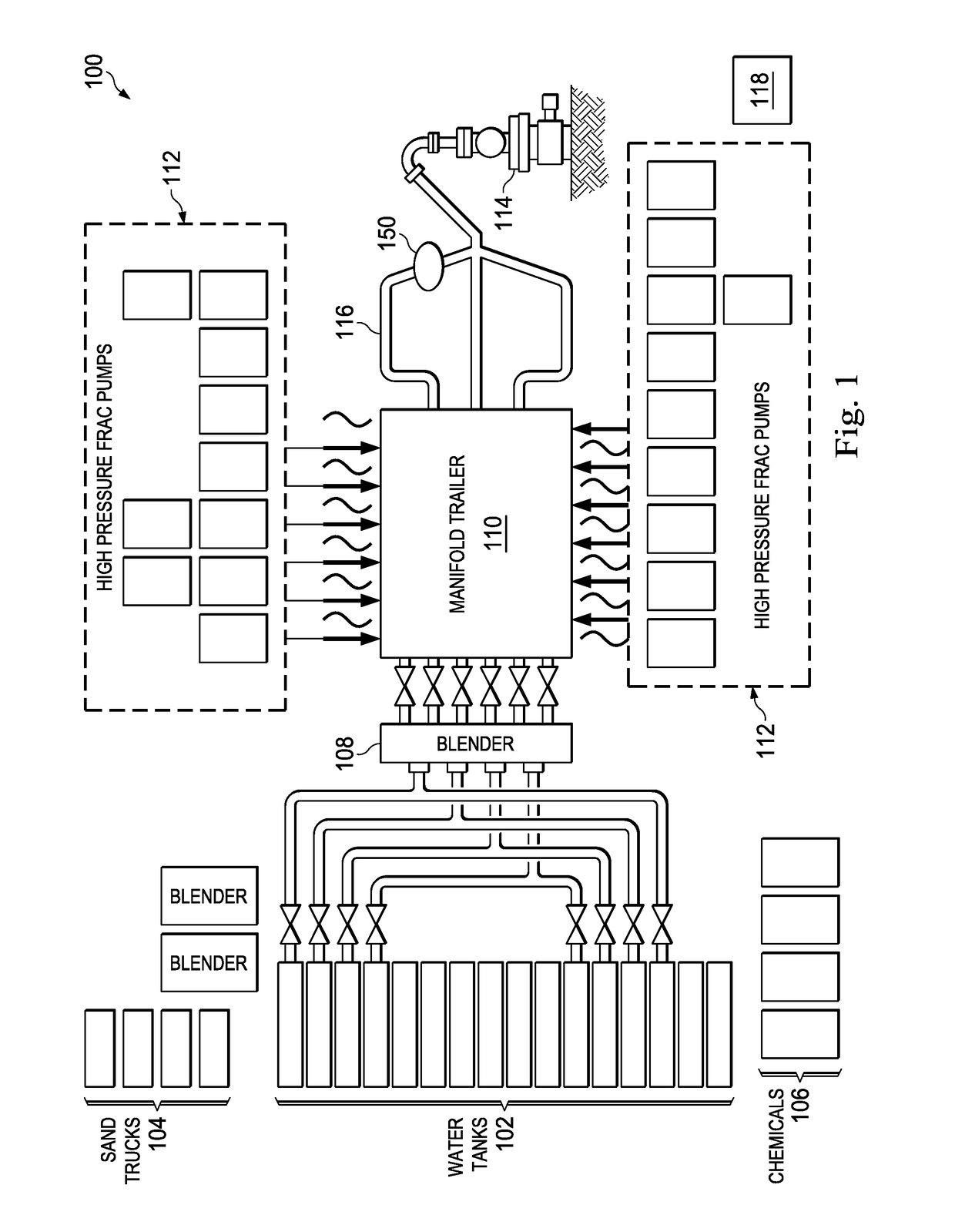
[0033]FIG. 1 illustrates an exemplary frac site incorporating subject matter of the present disclosure. The frac site, referenced herein by the numeral 100, includes water trucks 102, sand trucks 104, chemicals 106, a blender 108, a manifold trailer 110, and high pressure frac pumps 112. The water, sand, and chemicals are introduced into the blender 108 to create slurry referenced herein as a fracturing or fracing fluid. The fracing fluid is introduced into the manifold trailer 110, and fed from the manifold trailer 110 to high pressure frac pumps 112.

[0034]The manifold trailer 110 includes a low pressure section and a high pressure section. The low pressure section transfers low pressure from the blender 108 to the frac pumps 112. The high pressure section transfers the fracing fluid from the frac pumps 112 to a wellhead 114. The high pressure frac pumps 112 receive the mixed fluid from the manifold trailer 110 through respective suction manifolds and energize the fluid through res...


PUM


Abstract

A field pressure test control system is adapted to be coupled to high pressure tubing through which fluid is pumped to a wellhead. When the system is coupled to the tubing and an isolation valve is open, the tubing is in fluid communication with a fluid line via at least the isolation valve. A sensor detects pressure in the fluid line during pressure testing of the high pressure tubing, and a relief valve is opened to permit fluid flow through the relief valve and thus lower pressure in the high pressure tubing. A pressure testing method includes closing the wellhead, and pumping fluid into the high pressure tubing and the fluid line. A fluid pressure in the fluid line is detected, and a relief valve is remotely opened to lower the fluid pressure. In several exemplary embodiments, the pressure testing is completed before a hydraulic fracturing operation begins.

Description

CROSS-REFERENCE TO RELATED APPLICATIONS[0001]This application claims the benefit of the filing date of, and priority to, U.S. patent application No. 62 / 281,319, filed Jan. 21, 2016, the entire disclosure of which is hereby incorporated herein by reference.[0002]This application is related to U.S. patent application Ser. No. 15 / 005,438, filed Jan. 25, 2016, which is a continuation of U.S. patent application Ser. No. 13 / 964,863, filed Aug. 12, 2013, now U.S. Pat. No. 9,273,543, issued Mar. 1, 2016, which is a continuation-in-part of U.S. patent application Ser. No. 13 / 886,771, filed May 3, 2013, now U.S. Pat. No. 9,322,243, issued Apr. 26, 2016, which claims priority to and the benefit of the filing date of U.S. patent application No. 61 / 684,394, filed Aug. 17, 2012, the entire disclosures of which are hereby incorporated herein by reference.TECHNICAL FIELD[0003]This disclosure relates in general to a field pressure test control system and, in particular, to a field pressure test cont...

Claims


Application Information

Patent Timeline
IPC IPC(8): G05D16/20E21B41/00E21B34/00G01M3/28
CPCG05D16/2013G01M3/2807E21B33/03E21B34/00E21B43/26E21B41/00E21B34/02G01M3/2846E21B43/2607
Inventor SHELMAN, JOSHUAHURST, CODY
Owner S P M FLOW CONTROL
Why Eureka
Try Eureka