
Methods of mixing impeller sensing

a technology of impeller sensing and mixing, which is applied in the direction of rotary stirring mixers, instruments, transportation and packaging, etc., can solve the problems of damage to the mixing impeller, the mixing vessel and/or the motor, and the danger of mixing fluids

Active Publication Date: 2017-08-03
SARTORIUS STEDIM BIOTECH GMBH
View PDF0 Cites 6 Cited by
  • Summary
  • Abstract
  • Description
  • Claims
  • Application Information

AI Technical Summary

Benefits of technology

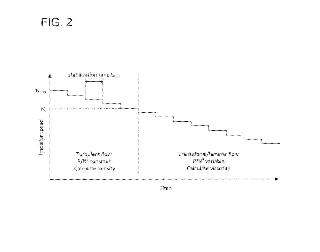
The described method uses a simple and inexpensive way to determine the density and viscosity of mixed components without needing further instrumentations or sampling. The method compensates for any variations that might occur during the process and reduces the speed of the mixing impeller to allow for a stable flow pattern. Additionally, the method can detect the presence of solids and prevent damage to the mixing impeller and vessel.

Problems solved by technology

However, some applications require that the mixing equipment is fully closed with no possibility of leakage between the mixing vessel and the environment—for example, the fluids to be mixed are either hazardous (e.g. toxic) or if they are sensitive to contamination from the outside environment (e.g. highly purified pharmaceutical material).
Although the solids are typically added to the liquid while the mixing impeller is rotating, there are situations in which the mixing impeller may be partially or fully obstructed by solid, like e.g. powder.
In this case, the mixing impeller is at least partly inoperable and damages may occur at the mixing impeller, the mixing vessel and / or the motor driving the mixing impeller.
Therefore, it is the underlying technical problem to provide a method for detecting solids at a mixing impeller which might block the mixing impeller and causes damages to the mixing system.
In the case that solids are settled into the space between the mixing impeller housing and the mounting depression, the resulting friction may prevent the mixing impeller from starting or it could generate particulate by grinding against the walls of the mixing impeller and the mounting depression.

Method used


Image

  • Methods of mixing impeller sensing
  • Methods of mixing impeller sensing
  • Methods of mixing impeller sensing

Examples


Embodiment Construction

[0087]In the following the disclosure is described with reference to particular embodiments.

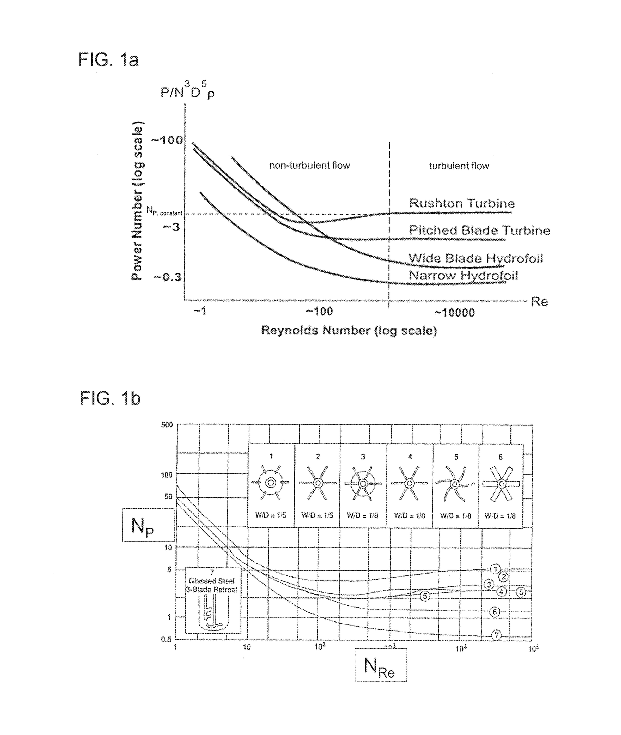
[0088]When mixing components such as two or more components in a mixing vessel, it is often important to monitor and / or determine a flow behaviour of mixed components being mixed by an impeller of a specific (predetermined or predeterminable) configuration, such as a Rushton impeller, within the mixing vessel having also a specific (predetermined or predeterminable) configuration. In a method of monitoring a flow behaviour of mixed components according to a particular embodiment of the invention use particularly is made of a Reynolds number NRe of the system (particularly corresponding to the specific impeller type and / or geometry used) and a Power number NP relative to a power applied to the impeller to rotate the impeller at a specified (predetermined or predeterminable) speed N.

[0089]The Reynolds number NRe particularly is a dimensionless number used in fluid dynamics to characterize the r...


PUM

PropertyMeasurementUnit
Reynolds numbersaaaaaaaaaa
Reynolds number NReaaaaaaaaaa
densityaaaaaaaaaa

Abstract

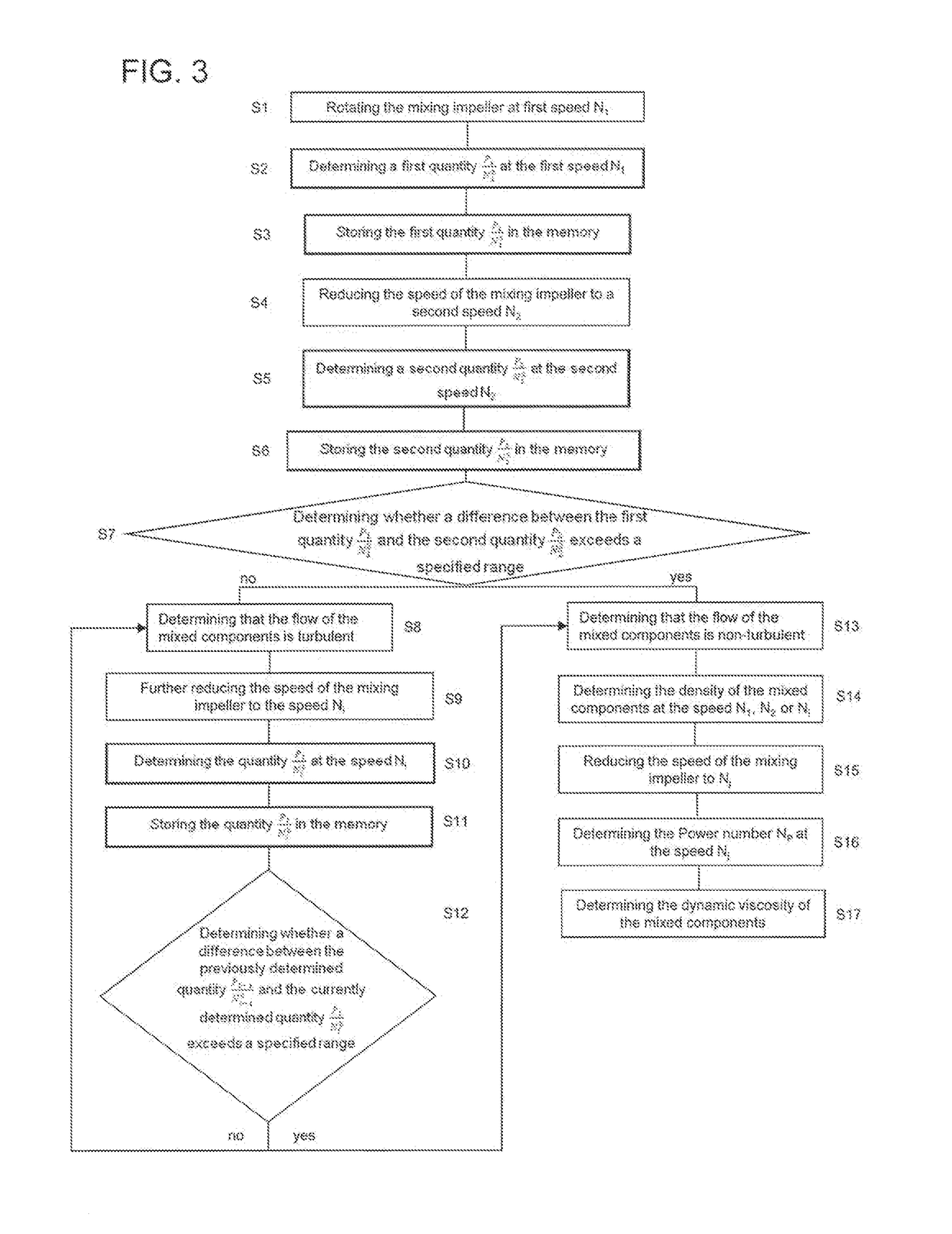
A method is provided for monitoring a flow behavior of mixed components without requiring additional instrumentation or sampling. The method is carried out by determining ratios of the power required to rotate a mixing impeller at different rotational speeds and then comparing the ratios. Characteristics about the mixed components are determined based on differences between the ratios.

Description

BACKGROUND[0001]1. Field of the Invention[0002]The invention relates to a method of monitoring a flow behaviour of components to be mixed, a control system and methods for detecting settled solids at a mixing impeller.[0003]2. Related Art[0004]Biopharmaceutical manufacturing requires mixing at several process steps, for example media preparation, buffer preparation, low pH viral inactivation of material between process steps. For this mixing step, usually the components to be mixed are accommodated in a mixing vessel in which a mixing impeller is provided. The mixing impeller is driven by a motor so that the mixing impeller is rotated. The mixing impeller usually comprises a rotationally symmetric mixing impeller basis and at least one mixing impeller blade that is attached to the mixing impeller basis. The mixing impeller blade extends radially or axially with respect to a rotation axis from the mixing impeller basis. The geometry and size of the mixing blade are chosen depending o...

Claims


Application Information

Patent Timeline
Patent Type & Authority Applications(United States)
IPC IPC(8): B01F15/00B01F13/08B01F3/12
CPCB01F15/00285B01F15/00201B01F15/00389B01F2215/0032B01F15/00246B01F3/1221B01F13/0818B01F15/00233C12M27/00G01N11/14B01F2215/0463B01F2215/0481G01N2001/386G01N2011/0006G01N2011/0026G01N2011/0053B01F2215/0409B01F23/53B01F33/453B01F27/90B01F35/212B01F35/2134B01F35/2136B01F35/221422B01F35/2202B01F33/452B01F2101/22
Inventor BOETTCHER, LARSCUTTING, JONATHAN E.WEST, SHARON D.OSCHWALD, MARTIN
Owner SARTORIUS STEDIM BIOTECH GMBH
Learn More