Hinge htr tube bracket

a technology of htr tube bracket and htr tube, which is applied in the direction of hose connection, machine support, other domestic objects, etc., can solve the problem of ensuring the distance between the conduit ends, and achieve the effect of better absorbed

Active Publication Date: 2017-08-03
HANON SYST
View PDF0 Cites 3 Cited by
  • Summary
  • Abstract
  • Description
  • Claims
  • Application Information

AI Technical Summary

Benefits of technology

[0011]Conceptually, a movable spacer is integrated into the fastening element by means of the film hinge. Advantages achievable with the invention are, in particular, a reduction in the required components, tool costs and assembly times. Such a fastening element is suitable both for conduit interfaces in left-hand drive vehicles (LHD) and in right-hand drive vehicles (RHD).
[0017]In order to support the fluid conduits in the direction of the respective conduit axis, the fastening element can have a support region above or below the plane and / or the extended plane of the conduit clamping region. In this way, the mounting forces at the conduit interface to the engine compartment can be better absorbed, in particular if the air conditioner housing does not provide suitable support in the direction of the conduit axis.
[0018]In this case, the support region is preferably designed to support curved fluid conduit lines with fluid conduit sections adjoining the fluid conduit ends, the conduit axis of which runs perpendicular to the conduit axis of the adjoining fluid conduit end in the direction of the respective conduit axis of these fluid conduit sections. With such an embodiment, the support region, according to an advantageous embodiment, has a rotated T-shaped cross-section transversely to the longitudinal direction of the U-shaped conduit clamping region with a vertical part and a horizontal part, below the plane and / or the extended plane of the U-shaped conduit clamping region. Thus, in the case of curved fluid conduits with fluid conduit sections neighboring the fluid conduit ends, the conduit axis of which runs perpendicular to that of the adjacent fluid conduit end, the support region is capable of partially accommodating two fluid conduit sections on both sides of the vertical part between the plane and / or the extended plane of the U-shaped conduit clamping region and the horizontal part, and of supporting these in the direction of the conduit axes of these fluid conduit sections.

Problems solved by technology

The disadvantage of the current prior art for the case where the mounting direction of the fastening element is in the direction of conduit ends lying one behind the other is, namely, that the distance between the conduit ends must be ensured by means of an additional component.

Method used


Image

  • Hinge htr tube bracket
  • Hinge htr tube bracket
  • Hinge htr tube bracket

Examples


Embodiment Construction

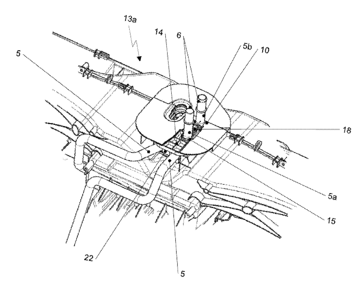
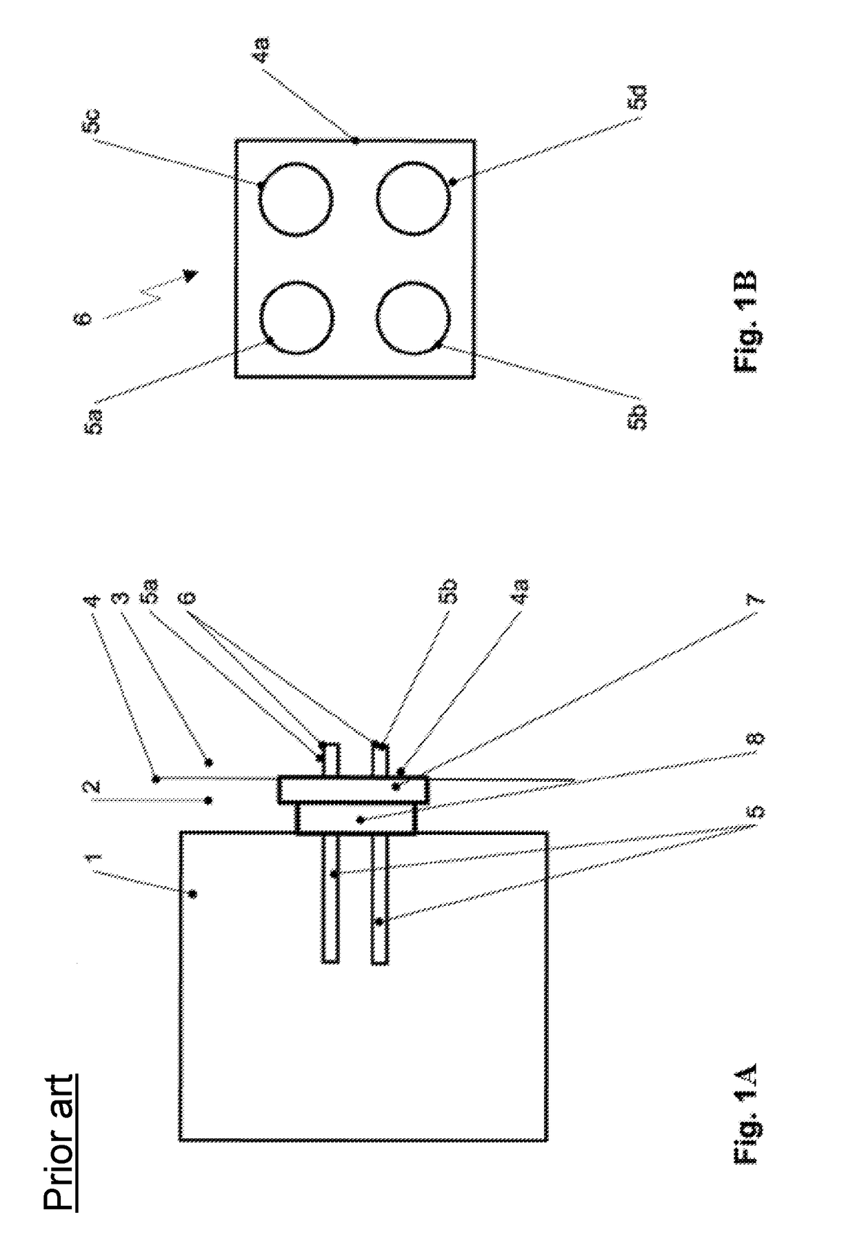
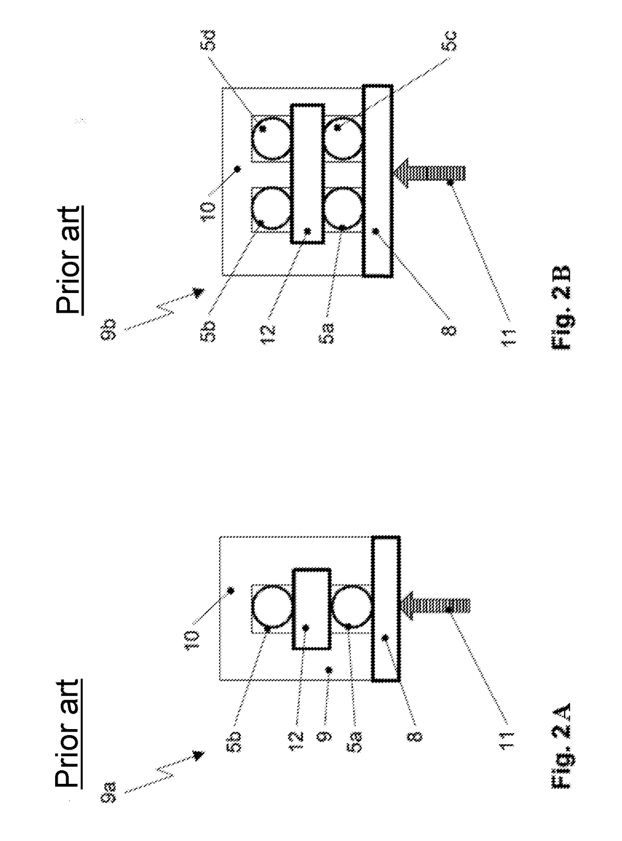
[0036]FIG. 1A schematically shows a general, prior art arrangement of an air-conditioning system 1 in a vehicle interior 2 near an adjacent engine compartment 3 of the vehicle, the vehicle interior 2 and the engine compartment 3 being spatially separated from one another by a front wall 4. The air conditioning system 1 generally contains a heat exchanger for heating the air and, if necessary, a further heat exchanger in the form of an evaporator for cooling the air. These two heat exchangers, which are not shown in FIG. 1, are supplied with fluid from the engine compartment 3 by means of fluid conduits. Between the air-conditioning system 1 and the connecting points of the engine-side fluid conduit ends, there is a conduit interface 6 or, respectively, a transfer point 6, wherein fluid conduit ends 5a, 5b are guided out of the air-conditioning system 1 through an opening 4a sealed with a seal 7 in the front wall 4. The fluid conduit ends 5a, 5b of the air conditioning system 1 must ...


PUM


Abstract

A fastening element for holding fluid conduit ends of a motor vehicle air conditioning system on an air conditioning system housing in a region of a conduit interface the fastening element including at least one U-shaped conduit clamping region between two opposing U-leg regions connected to one another by a curved or straight U-shaped base region, wherein at least one fluid conduit end, which is aligned with its conduit axis perpendicular to the longitudinal direction of the U-shaped conduit clamping region, can be clamped in the U-shaped conduit clamping region. At least one pivotable spacer is connected as an integrated component of the fastening element to one of the U-leg regions by means of a film hinge, and is capable of at least partially filling and / or bridging the U-shaped conduit clamping region by means of a pivoting movement in the direction of the respectively opposite U-leg region.

Description

CROSS-REFERENCE TO RELATED PATENT APPLICATION[0001]This patent application claims priority to German Pat. Appl. No. 10 2016 101 603.9 filed Jan. 29, 2016, the disclosure of which is hereby incorporated herein by reference in its entirety.FIELD OF THE INVENTION[0002]The invention relates to a fastening element for holding fluid conduit ends of a motor vehicle air conditioning system on an air conditioning system housing in the region of a conduit interface. Furthermore, the invention relates to a method for attaching fluid conduit ends to an air conditioning system housing in the region of a conduit interface.BACKGROUND OF THE INVENTION[0003]An air conditioning system includes a heat exchanger for heating air in the form of a heating heat exchanger and, if appropriate, a heat exchanger for cooling the air in the form of an evaporator. These heat exchangers are supplied with appropriate media, such as refrigerants, via fluid conduit ends coming from the engine compartment. A motor veh...

Claims


Application Information

Patent Timeline
Patent Type & Authority Applications(United States)
IPC IPC(8): B60R16/08F16L3/237B60H1/00F16L3/10
CPCB60R16/08B60H1/00521F16L3/237F16L3/1075B60H1/00571F16L3/22B60H1/00557B60R16/02F16L33/22F16L55/00
Inventor HOFFMANN, MICHAELWIESMANN, RALPHFERREIRA, ANTONIO MARQUES
Owner HANON SYST
Why Eureka
Try Eureka