Eureka AIR delivers breakthrough ideas for toughest innovation challenges, trusted by R&D personnel around the world.

Device and method for determining the diameter of a yarn balloon formed by a continuous yarn at a workstation of a yarn balloon forming textile machine

Active Publication Date: 2017-08-03
SAURER TECH GMBH & CO KG
View PDF8 Cites 2 Cited by
  • Summary
  • Abstract
  • Description
  • Claims
  • Application Information

AI Technical Summary

Benefits of technology

The invention aims to develop a method or device that can accurately and reliably determine the diameter of a yarn balloon formed by continuous yarn. The device should be simple and cost-effective.

Problems solved by technology

The method described in German Patent Publication DE 101 03 892 A1 is however used only for scanning the limit values for the balloon size, but provides no information about the balloon size at all times during the process.
The known devices are either relatively complicated (German Patent Publication DE 22 55 663 A1) and often also quite inaccurate, or they are very sensitive with regard to air pollution due to their large measuring range (German Patent Publication DE 101 03 892 A1).
In practice these known devices have thus not been able to prove themselves.
The method described in European Patent Publication EP 0 282 745 A1 also occasionally works rather imprecisely, as the beam bundle is often negatively influenced by fiber and dust particles, which are almost unavoidable in the atmosphere of a spinning room, on its way from the transmitter to the receiver.
The chosen arrangements of the monitoring organ also do not allow a conclusion with regard to the balloon diameters.
However, the known embodiment is used only for scanning the limit values for the balloon size and gives no exact indication of the size of the yarn balloon at any time of the spooling process.
With such an embodiment different reflections are however possible, depending on the yarn thickness, yarn surface and / or yarn twists, which negatively influence the error quota and resolution of the measurement.
CCD receivers also represent relatively costly equipment, as they require a complex evaluation unit for their operation.
The monitoring means described in European Patent Publication EP 2 419 554 B1 in connection with a workstation of a double-wire twisting and cabling machine are all improvable, as they either do not measure precisely enough or are relatively costly.

Method used


Image

  • Device and method for determining the diameter of a yarn balloon formed by a continuous yarn at a workstation of a yarn balloon forming textile machine
  • Device and method for determining the diameter of a yarn balloon formed by a continuous yarn at a workstation of a yarn balloon forming textile machine
  • Device and method for determining the diameter of a yarn balloon formed by a continuous yarn at a workstation of a yarn balloon forming textile machine

Examples


Embodiment Construction

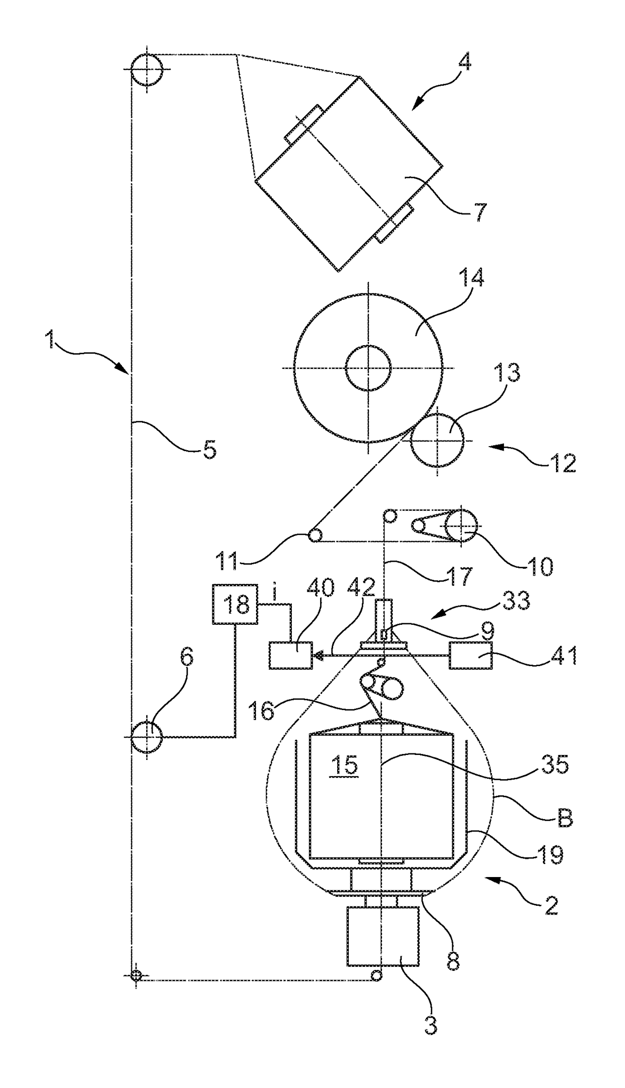
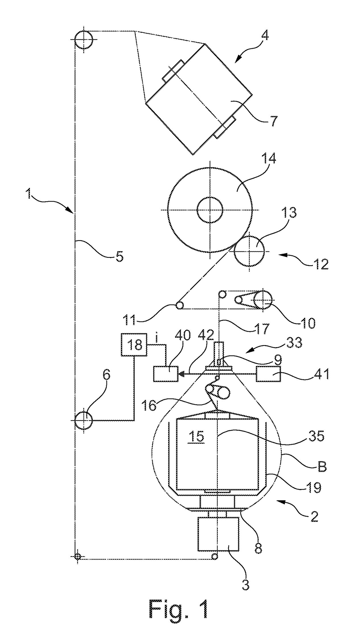
[0061]A schematic side view of a workstation 1 of a double-wire twisting or cabling machine is illustrated in FIG. 1. In this embodiment the textile machine comprises a creel 4, which is normally positioned above or behind the workstation 1 and normally serves for receiving a multitude of feed packages. A so-called outer yarn 5 is extracted from one of the feed packages, hereafter described as the first feed package 7.

[0062]The workstation 1 further has a spindle 2, rotatable around an axis of rotation 35, in the present embodiment example consisting of a cabling spindle equipped with a protective cap 19, in which a second feed package 15 is stored.

[0063]A so-called inner yarn 16 is extracted overhead from this second feed package 15, and is supplied to a yarn balloon guiding eye or a so-called balancing system 9 arranged above the spindle 2. The protective cap 19, mounted on the yarn diverting means designed as a rotatable twisted yarn plate 8 in this embodiment example, is prefera...


PUM


Abstract

A device as well as a method for determining the diameter of a yarn balloon (B) formed by a continuous yarn at a workstation (1) of a yarn balloon forming textile machine. The workstation (1) comprises an electromagnetically functioning sensor means (33), designed and arranged in such a way that at least two interruptions of a measuring beam (42) of the sensor means (33) are caused by the yarn (5, 25) forming the yarn balloon (B) during every rotation of the yarn balloon (B) during the operation of the workstation (1), and in that the time interval between the interruptions of the measuring beam (42) can be recorded by the sensor means (33) and used for calculating the diameter of the yarn balloon (B).

Description

CROSS-REFERENCE TO RELATED APPLICATIONS[0001]This application claims priority from German National Patent Application No. DE 10 2016 001 099.1, filed Feb. 2, 2016, entitled “Vorrichtung and Verfahren zum Ermitteln des Durchmessers eines durch einen laufenden Faden gebildeten Fadenballons an einer Arbeitsstelle einer fadenballonbildenden Textilmaschine”, the entire contents of which are incorporated herein by reference.FIELD OF THE INVENTION[0002]The present invention concerns a device for determining the diameter of a yarn balloon formed by a continuous yarn at a workstation of a yarn balloon forming textile machine as well as an associated method.BACKGROUND OF THE INVENTION[0003]Various embodiments of production machines, where a yarn balloon is formed in the area of their often numerous workstations or at associated operating means during operation, have been known for a long time within the textile machine industry.[0004]Such production machines therefore comprise monitoring mean...

Claims


Application Information

Patent Timeline
IPC IPC(8): B65H63/028B65H63/08
CPCB65H63/082B65H63/028D01H13/16D01H13/32B65H59/00D01H1/425D01H7/18D01H13/104B65H49/02B65H63/00B65H2701/31B65H2553/46B65H2553/80B65H2511/14
Inventor HIEPP, MAGNUSPEDE-VOGLER, WALTERTHALER, ALEXANDER
Owner SAURER TECH GMBH & CO KG
Why Eureka
Eureka Blog
Learn More