Supercharge Your Innovation With Domain-Expert AI Agents!

Conductive wafer lift pin o-ring gripper with resistor

a technology of resistors and lift pins, applied in the direction of electrical equipment, basic electric elements, electric discharge tubes, etc., can solve the problems of damage or breakage of substrates by upward pushing lift pins

Active Publication Date: 2017-08-03
APPLIED MATERIALS INC
View PDF6 Cites 9 Cited by
  • Summary
  • Abstract
  • Description
  • Claims
  • Application Information

AI Technical Summary

Benefits of technology

The present disclosure relates to a lift pin assembly for de-chucking substrates used in plasma processing chambers. The lift pin assembly includes a base and one or more lift pin holders. Each lift pin holder has a first and second portion and a resistor is disposed in the first portion. The second portion has a support for the lift pin which is electrically conductive. The base is connected to a reference voltage to form a path for residual electrostatic charge in the substrate. The technical effects of the invention are improved substrate de-chucking performance, reduced substrate damage, and improved substrate handling in plasma processing chambers.

Problems solved by technology

One problem with conventional lift pins arises when the lift pins attempt to lift the substrate off the chuck.
The upwardly pushing lift pins can damage or break the substrate.

Method used


Image

  • Conductive wafer lift pin o-ring gripper with resistor
  • Conductive wafer lift pin o-ring gripper with resistor
  • Conductive wafer lift pin o-ring gripper with resistor

Examples


Embodiment Construction

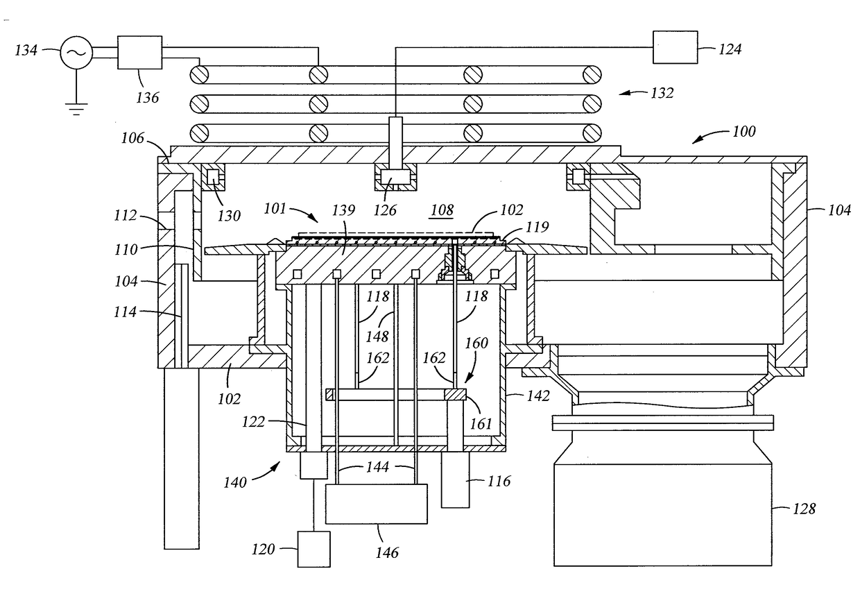
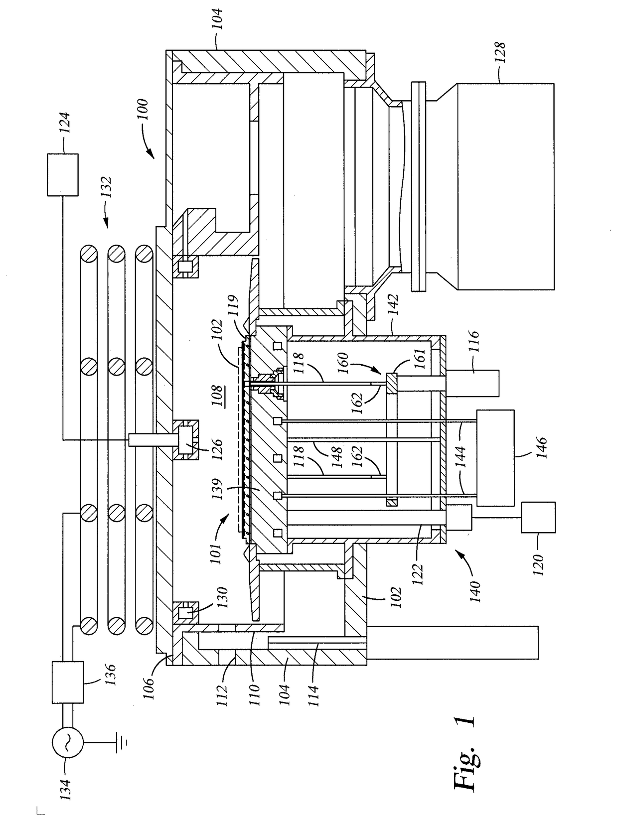
[0020]FIG. 1 is a schematic, cross-sectional view of a plasma processing chamber 100 within which the method described herein may be performed. The substrate support assembly 101 may be used to support a variety of substrates, such as semiconductor substrates and reticles. The substrate support assembly 101 may include an electro-static chuck assembly.

[0021]The plasma processing chamber 100 includes a bottom 102, a sidewall 104 and a chamber lid 106 disposed over the sidewall 104 defining a processing volume 108. The plasma processing chamber 100 further includes a liner 110 disposed in the processing volume 108 to prevent the sidewall 104 from damage and contamination from the processing chemistry and / or processing by-products. A slit valve door opening 112 is formed through the sidewall 104 and the liner 110 to allow passage of the substrates and substrate transfer mechanism disposed in a system, such as a cluster tool (as described in FIG. 2) that is coupled to the plasma process...


PUM

PropertyMeasurementUnit
temperatureaaaaaaaaaa
conductiveaaaaaaaaaa
volumeaaaaaaaaaa

Abstract

Embodiments of the present disclosure generally relate to a lift pin assembly used for de-chucking substrates. The lift pin assembly includes a base and one or more lift pin holders. Each lift pin holder includes a first portion and a second portion. The first portion is coupled to the base by a metal connector and the second portion is coupled to the first portion by a metal connector. A resistor is disposed in the first portion of the lift pin holder. The second portion includes a lift pin support for supporting a lift pin. The lift pin, the lift pin support, and the metal connectors are electrically conductive. The base is connected to a reference voltage, such as the ground, forming a path for the residual electrostatic charge in the substrate from the substrate to the reference voltage.

Description

CROSS-REFERENCE TO RELATED APPLICATIONS[0001]This application claims priority to U.S. Provisional Patent Application Ser. No. 62 / 288,288, filed on Jan. 28, 2016, which herein is incorporated by reference.BACKGROUND[0002]Field[0003]Embodiments of the present disclosure generally relate to apparatus for forming a semiconductor device. More particularly, embodiments described herein relate to a lift pin assembly used for de-chucking substrates.[0004]Description of the Related Art[0005]In semiconductor processing, lift pins are used to lift and lower a semiconductor substrate onto a chuck that is used to hold the substrate in a process chamber. Typically, a robotic arm transports the substrate into an upper portion of the process chamber where the substrate is deposited on lift pins that extend upwardly through the chuck. The lift pins are then lowered into a lower portion of the process chamber to place the substrate on the chuck. Thereafter, the robotic arm is withdrawn from the chamb...

Claims


Application Information

Patent Timeline
Patent Type & Authority Applications(United States)
IPC IPC(8): H01L21/687H01J37/32H01L21/683
CPCH01L21/68742H01L21/6831H01J37/32183H01J37/3211H01J37/32715
Inventor COTLEAR, ROBERTO CESARWILLWERTH, MICHAEL D.
Owner APPLIED MATERIALS INC
Features
  • R&D
  • Intellectual Property
  • Life Sciences
  • Materials
  • Tech Scout
  • Unparalleled Data Quality
  • Higher Quality Content
  • 60% Fewer Hallucinations
Learn More