System and method of determining process completion of post heat treatment of a dry etch process

a dry etching and process completion technology, applied in the direction of basic electric elements, electrical equipment, semiconductor/solid-state device testing/measurement, etc., can solve the problems of inability to determine real-time in-situ, inability to real-time methods, and prone to errors in dry etching process results, so as to increase the throughput of substrates and increase the uniformity of removal of byproduct layers.

Active Publication Date: 2017-08-03
TOKYO ELECTRON LTD
View PDF4 Cites 7 Cited by
  • Summary
  • Abstract
  • Description
  • Claims
  • Application Information

AI Technical Summary

Benefits of technology

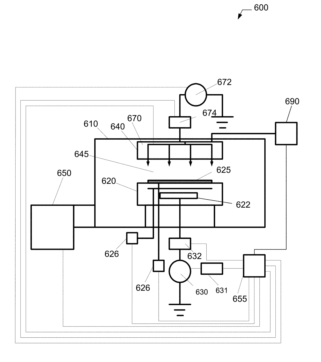
[0010]Moreover, provided is a fabrication system configured to determine and utilize process completion data of a PHT of a dry etch process for use in process control, the fabrication system comprising: a process chamber of a PHT (PHT) system; a chemical oxide removal (COR) or atomic layer etch (ALE) system coupled to the PHT system; and a controller coupled to the PHT and to the COR or ALE system; wherein the COR system processes a substrate by performing a dry etch process to remove the film layer or region of the film layer, the dry etch process generating a byproduct layer; and by performing a PHT (PHT) process to remove the byproduct layer on the substrate; and wherein the PHT process utilizes a real time in-situ process to concurrently determine when removal of the byproduct layer is complete. The controller also receives PHT drying completion information from the PHT system and utilizes the PHT drying completion information to adjust one or more operating variables in the PHT system in order to increase the uniformity of removal of the byproduct layer and increase substrate throughput.

Problems solved by technology

Processes such as dry chemical etching PHT do not currently have a method to determine real time in-situ complete sublimation of etch byproduct layers.
This ‘timed’ method is not real time and is therefore prone to error when taking into account film variations, process chamber conditioning, and process changes.

Method used


Image

  • System and method of determining process completion of post heat treatment of a dry etch process
  • System and method of determining process completion of post heat treatment of a dry etch process
  • System and method of determining process completion of post heat treatment of a dry etch process

Examples


Embodiment Construction

[0019]Methods and systems for patterning sidewall shapes are presented. However, one skilled in the relevant art will recognize that the various embodiments may be practiced without one or more of the specific details, or with other replacement and / or additional methods, materials, or components. In other instances, well-known structures, materials, or operations are not shown or described in detail to avoid obscuring aspects of various embodiments of the invention.

[0020]Similarly, for purposes of explanation, specific numbers, materials, and configurations are set forth in order to provide a thorough understanding of the invention. Nevertheless, the invention may be practiced without specific details. Furthermore, it is understood that the various embodiments shown in the figures are illustrative representations and are not necessarily drawn to scale. In referencing the figures, like numerals refer to like parts throughout.

[0021]Reference throughout this specification to “one embod...


PUM


Abstract

Provided is a method for determining and utilizing process completion of PHT (PHT) of a dry etch process, the method comprising: providing a substrate in a process chamber, the substrate having a film layer and an underlying layer, the film layer having one or more regions; performing a dry etch process to remove the film layer or region of the film layer, the dry etch process generating a byproduct layer; and measuring one or more properties of the byproduct layer; adjusting the PHT process based on the measured one or more properties of the byproduct layer; performing the PHT process to remove the byproduct layer on the substrate; wherein the PHT process utilizes a real time in-situ process to concurrently determine when removal of the byproduct layer is complete.

Description

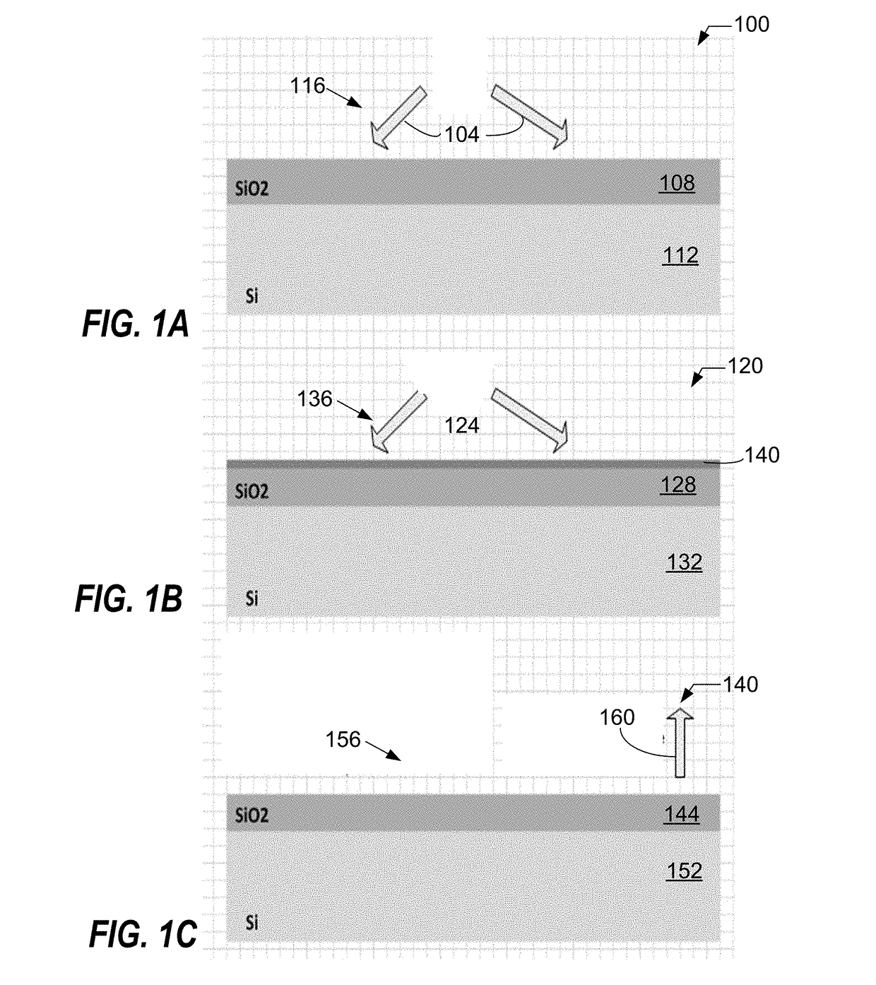
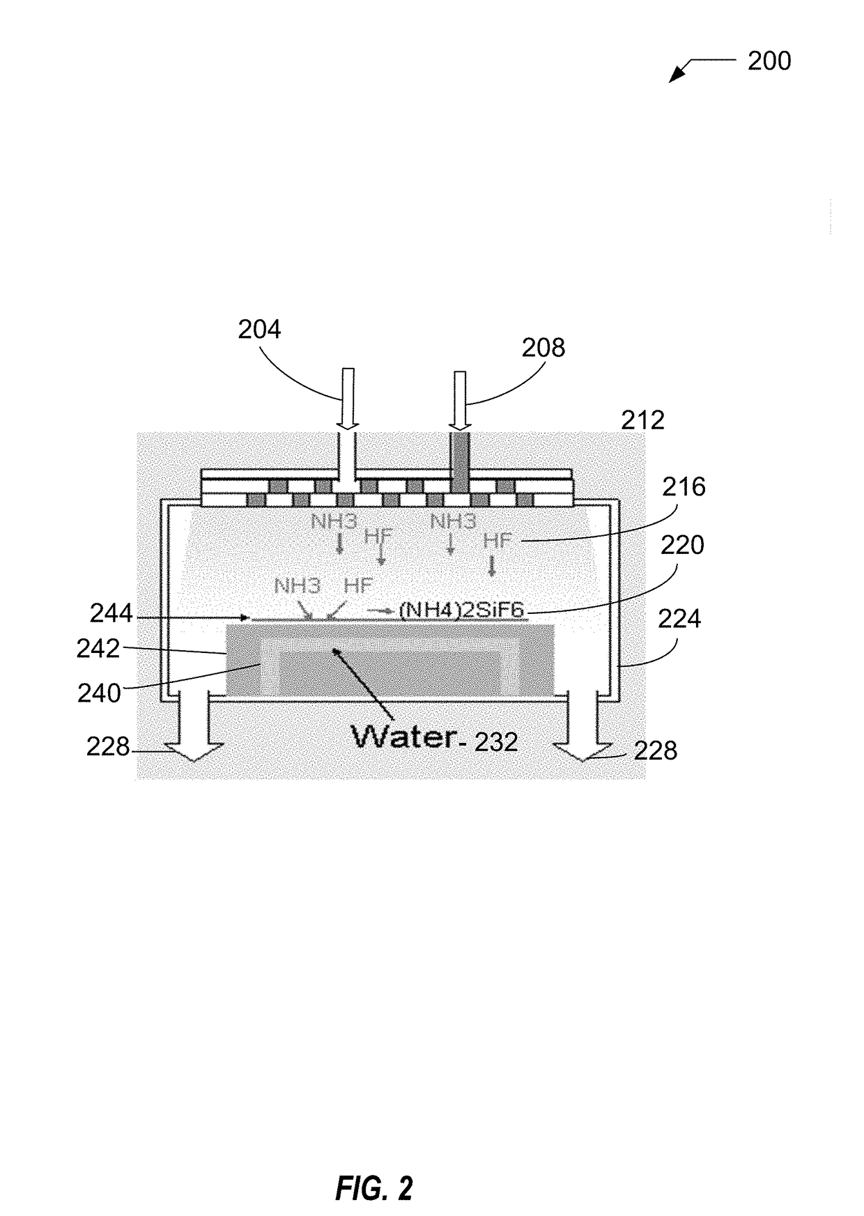
CROSS-REFERENCE TO RELATED APPLICATIONS[0001]This application is related to and claims priority to U.S. Provisional Application No. 62 / 184,003, filed Jun. 24, 2015, the entire contents of which are herein incorporated by reference.BACKGROUND OF THE INVENTION[0002]Field of Invention[0003]The present invention relates to a system and method for substrate processing, and more particularly to a method and system for determining the endpoint of post heat treatment (PHT) and to use endpoint data for process control.[0004]Description of Related Art[0005]This invention relates to dry chemical etching of thin films that require PHT. When thin films are removed using dry chemical etching a byproduct layer is left behind on the substrate's surface. Removal of this byproduct layer or film is mostly done using high temperature PHT. It would be highly advantageous to know in real time when the byproduct layer has been removed and would significantly increase process control, increase throughput, ...

Claims


Application Information

Patent Timeline
Patent Type & Authority Applications(United States)
IPC IPC(8): H01L21/66H01L21/67H01L21/3065H01L21/311
CPCH01L21/31116H01L21/67103H01L21/67115H01L22/26H01L21/67253H01L21/3065H01L21/67069H01L22/12
Inventor THEISEN, JACOBMOSDEN, AELAN
Owner TOKYO ELECTRON LTD
Why Eureka
Try Eureka