Device and method for the manufacture or repair of a three-dimensional object

a three-dimensional object and device technology, applied in the field of three-dimensional object devices, can solve the problems of non-uniform flow rate over the nozzle width, and insufficient removal of process by-products, so as to increase the flow rate, reduce the flow resistance in the flow channel, and increase the flow rate

Active Publication Date: 2018-10-30
MTU AERO ENGINES GMBH
View PDF7 Cites 18 Cited by
  • Summary
  • Abstract
  • Description
  • Claims
  • Application Information

AI Technical Summary

Benefits of technology

[0008]In other advantageous embodiments of the device according to the invention, the suction nozzle comprises at least one suction orifice, which is connected to an associated suction channel in such a way as to carry the flow, with the flow channel having wall surfaces that, in the flow direction, have a contoured course that is curved at least in sections. The avoidance of corners and edges within the flow channel results, in turn, in an increase in the flow rate, because the flow resistance within the flow channel is markedly reduced by the curved contoured course of the wall surfaces, that is, the corresponding roundings thereof. Furthermore, there exists the possibility that the suction nozzle comprises at least two suction orifices, with the associated suction channels being separated from one another at least in sections. In this case, the suction channels are designed and dimensioned in such a way that a roughly equivalent gas volume flow passes through each suction channel. This measure also results, on the one hand, in an increased flow rate in the flow channels and, on the other hand, in a more homogeneous flow field in the construction chamber of the device. Furthermore, there exists the possibility that the suction channel is designed in such a way that the suctioned gas flow is diverted in a plane above and / or below the suction orifice. For this purpose, the flow is carried after the inlet into the suction channel first upward and / or downward and then to the side. This advantageous embodiment results in a more compact construction design of the suction nozzle, which leads overall to a simplification in the design of the device. Furthermore, there exists the possibility that the suction nozzle comprises a plurality of suction orifices, with at least one cover being arranged on a subregion of the suction orifices in order to reduce the fluid-dynamically relevant cross-sectional area. In this case, the cover can be designed as a separate component, although it is also possible to cover the mentioned subregion of the suction orifices with a corresponding adhesive film. All in all, the design of the suction nozzles according to the invention results in a marked reduction in the sum of the fluid-dynamically relevant cross-sectional areas, in particular the area of the corresponding suction orifices of the suction nozzle. The design of the suction nozzles according to the invention results in a marked increase in the flow rate of the gas flow at the suction, so that process by-products formed in the construction chamber of the device can be removed in a straightforward manner.
[0009]In other advantageous embodiments of the device according to the invention, the device comprises at least one upper inlet nozzle arranged in an upper region lying opposite the construction platform and / or in a side wall of the device, and / or at least one lower inlet nozzle arranged in a side wall of the device above the construction platform and below the upper inlet nozzle. Depending on the volume of the construction chamber, the inlet nozzles can be arranged advantageously in different regions and also in a requisite number for achieving a corresponding flow volume of the process gas. In this case, the upper inlet nozzle can comprise at least two inlet orifices, with the inlet orifices being separated by at least one separator wall. The incoming gas flow of the process gas is divided in the inlet nozzle and carried into the individual inlet channels. In this case, the division of the gas flow can occur, for example, by horizontally and / or vertically arranged separator walls. In addition, the inlet channels can be designed in such a way that the outflow rate is the same at each point of the inlet nozzle. In this case, the nozzle width is chosen advantageously in such a way that it leads to a flow field of the process gas that is distributed homogeneously on the entire construction platform. This results overall in an improvement in the homogeneity of the flow field of the process gas within the construction chamber and, in particular, above the construction platform of the device. In another advantageous embodiment of the upper inlet nozzle, it comprises at least one passage opening for a high-energy beam, in particular a laser beam or electron beam, or a light beam, in particular a UV light beam. In this case, the flow of the process gas is, in turn, divided in the inlet nozzle by separator walls and diverted in the direction of the construction platform. In particular, in a lateral arrangement of the upper inlet nozzle, the gas flow is diverted by approximately 90° downward in the direction of the construction platform. Such an embodiment of the upper inlet nozzle makes possible, in turn, an overall compact design of the device.
[0012]A third aspect of the invention relates to an inlet nozzle for use in a device for the additive manufacture or repair of a three-dimensional object, said inlet nozzle comprising at least two inlet orifices and the inlet orifices being separated from each other by at least one separator wall. According to the invention, an incoming gas flow of a process gas is divided in the inlet nozzle and carried into individual inlet channels. In this case, the division of the gas flow can occur, for example, by horizontally and / or vertically arranged separator walls. In addition, the inlet channels can be designed in such a way that the outflow rate is the same at each point of the inlet nozzle. In this case, the nozzle width is chosen advantageously in such a way that it leads to flow field of the process gas that is distributed homogeneously on an entire construction platform of the device for the additive manufacture or repair of a three-dimensional object. This results overall in an improvement in the homogeneity of the flow field of the process gas within the construction chamber and, in particular, above the construction platform of the device. In another advantageous embodiment of the upper inlet nozzle, it comprises at least one passage opening for a high-energy beam, in particular a laser beam or electron beam, or a light beam, in particular a UV light beam. In this case, the flow of the process gas is, in turn, divided in the inlet nozzle by separator walls and diverted in the direction of the construction platform. In particular, in a lateral arrangement of the upper inlet nozzle, the gas flow is diverted by approximately 90° downward in the direction of the construction platform. Such an embodiment of the upper inlet nozzle makes possible, in turn, an overall compact design of the device. The embodiment of the inlet nozzle according to the invention results in a marked improvement in the homogeneity of the flow field of the process gas above the construction platform in the construction chamber, so that process by-products that are formed in the construction chamber of the device can be removed uniformly in a straightforward manner.

Problems solved by technology

In this case, the centered arrangement of the upper inlet nozzle in the upper region of the device can lead to an inhomogeneous flow field and thus to a deficient removal of process by-products.
Known geometries of suction nozzles can lead to non-uniform flow rates over the nozzle width.
The mentioned low flow rates as well as the overall inhomogeneous flow field within the construction spaces of known devices lead to a deficient removal of process by-products.
Thus, in known devices for selective laser beam melting, flaws in the process and in the component increasingly occur in certain construction space regions, so that these regions are not suitable for the production of serially manufactured components.
These flaws occur, in particular, owing to the mentioned deficient removal of process by-products.
As a result, the energy density that needs to be introduced onto the melting material drops and the powder is melted only deficiently.
This leads to deficient bonding to the component, as a result of which, in turn, bonding flaws can occur in the component.
In addition, spatter and ejected material lead to a marked local increase in the layer thickness.
As a result, in turn, a deficient bonding to the component and bonding flaws can occur.

Method used


Image

  • Device and method for the manufacture or repair of a three-dimensional object
  • Device and method for the manufacture or repair of a three-dimensional object
  • Device and method for the manufacture or repair of a three-dimensional object

Examples


first embodiment

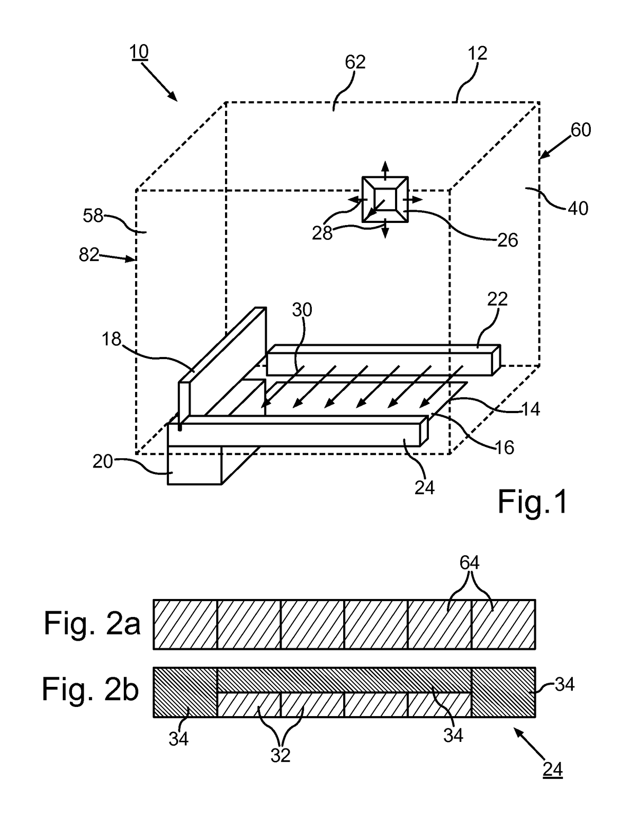
[0034]FIG. 2a shows a schematic illustration of a suction nozzle according to the prior art. The design as well as the area of the suction orifices 64 are seen. Schematically illustrated in comparison to this in FIG. 2b is the suction nozzle 24 for use in the device 10. It is seen that the suction nozzle 24 comprises a plurality of suction orifices 32, with a subregion of the suction orifices 32 being closed by means of the covers 34. In the illustrated exemplary embodiment, the covers 34 are composed of an adhesive film, for example. The at least partial covering of the suction orifices 32 results, in comparison to the suction nozzle illustrated in FIG. 2a according to the prior art, in a marked reduction in the fluid-dynamically relevant cross-sectional area of the suction nozzle 24. In the illustrated exemplary embodiment, approximately 66% of the original suction orifices 64 are covered, so that there results a roughly threefold increase in the flow rate at the suction. In comp...

second embodiment

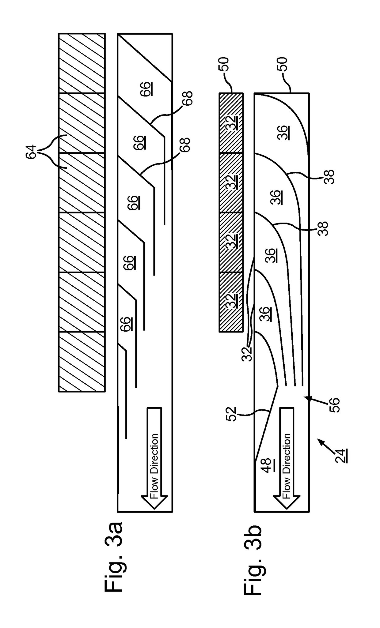
[0036]In contrast to this, FIG. 3b shows, in a schematic illustration, the suction nozzle 24 for use in the device 10. Initially evident is the reduced cross-sectional areas of the suction orifices 32 in comparison to the known suction nozzle according to FIG. 3a. In addition, it is clear in the schematically illustrated and cut-away plan view of the suction nozzle 24, which is likewise appended, that flow channels 36 are formed, in turn, within a casing 50 of the suction nozzle 24, and said flow channels are connected to the corresponding suction orifices 32 in such a way as to carry the flow. In this case, the flow channels 36 are formed by wall surfaces 38 and separated from one another, with the wall surfaces 38 having a contoured course that is curved at least in sections in the flow direction. In contrast to the walls 68 shown in FIG. 3a, the wall surfaces 38 are not bent and do not exhibit any corresponding corner regions. The wall surfaces 38 exhibit a rounded course, which...

third embodiment

[0037]FIG. 4 shows a schematic illustration of a suction nozzle 24 for use in the device 10. Evident once again is the design of the suction orifices 32, which are connected to corresponding flow channels 36 in such a way as to carry the flow. The flow direction of the gas flow is indicated by the arrows. Furthermore, it is seen that the suction channels 36 are designed in such a way that the suctioned gas flow is carried in a plane above the suction orifices 32. The suction orifices 32 are designed with a smaller cross-sectional area in comparison to the known suction nozzles. The flow channels 36 are once again formed by wall surfaces 38, which exhibit a contoured course that is curved at least in sections in the flow direction. The casing 50 of the suction nozzle 24 is divided into a lower casing section 54a and an upper casing section 54b in the illustrated exemplary embodiment, with the suction channel 36 being passed from the lower casing section 54a into the upper casing sec...


PUM

PropertyMeasurementUnit
effective flow ratesaaaaaaaaaa
flow ratesaaaaaaaaaa
volumeaaaaaaaaaa

Abstract

The invention relates to a device for the manufacture or repair of a three-dimensional object, comprising at least one construction chamber for a successive solidification of at least one solidifiable material layer by the layer in predefined regions for the layer-by-layer buildup of the three-dimensional object or for the layer-by-layer repair of individual regions of the three-dimensional object within the construction chamber, and at least one inlet nozzle and at least one suction nozzle for a process gas, wherein the inlet nozzle and the suction nozzle are arranged in such a way that a gas flow that passes at least partially over a construction platform formed in a construction chamber is created.

Description

BACKGROUND OF THE INVENTION[0001]The invention relates to a device for the manufacture or repair of a three-dimensional object in accordance with the present invention. The invention further relates to a suction nozzle and an inlet nozzle for use in a device for the additive manufacture or repair of a three-dimensional object also in accordance with the present invention.[0002]Methods and devices for the manufacture of three-dimensional objects, in particular components, are known in great variety. In particular, additive manufacturing methods (so-called rapid manufacturing or rapid prototyping methods) are known, in which the three-dimensional object or the component is built up layer by layer by means of additive manufacturing methods based on powder beds. Primarily metal components can be manufactured by laser or electron-beam melting or sintering methods, for example. In these processes, at least one powdered component material is deposited initially layer by layer on a componen...

Claims


Application Information

Patent Timeline
Patent Type & Authority Patents(United States)
IPC IPC(8): B22F3/105B28B1/00B33Y30/00B22F7/06B29K105/00
CPCB22F3/1055B28B1/001B22F2003/1056Y02P10/295B29K2105/251B33Y30/00B22F2007/068Y02P10/25B22F10/28B22F12/70B22F10/322
Inventor SCHLICK, GEORGFISSER, MAXIMILIANLADEWIG, ALEXANDERSCHLOTHAUER, STEFFENHESS, THOMASJAKIMOV, ANDREAS
Owner MTU AERO ENGINES GMBH
Why Eureka
Try Eureka