Fuel cell

Inactive Publication Date: 2005-06-02
TOYOTA JIDOSHA KK
View PDF6 Cites 18 Cited by
  • Summary
  • Abstract
  • Description
  • Claims
  • Application Information

AI Technical Summary

Benefits of technology

[0030] With the fuel cell according to item (e) above, since at least a portion of the reactant gas passage-side surface of the separator is formed

Problems solved by technology

The product water increases in amount in a downstream portion of the oxidant gas passage and is likely to cause flooding.
In the flooding region, supply of the oxidant gas to cathode is obstructed, and the above-described reaction does not occur smoothly.
A similar problem occurs with the fuel gas passage, since a portion of the water in the oxidant gas passage move through the electrolyte membrane into the fuel gas passage.
Therefore, flooding is more likely to occur.
In a case where the cooling water is anti-freeze coolant, some components in the coolant may damage the electrolyte membrane when the coolant moves to the

Method used


Image

  • Fuel cell
  • Fuel cell
  • Fuel cell

Examples


embodiment 1

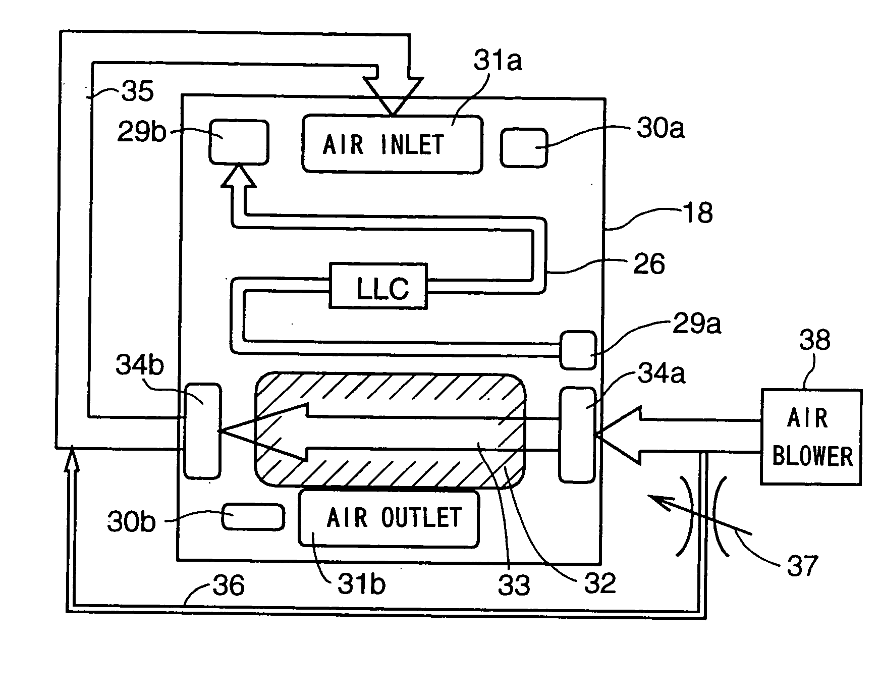
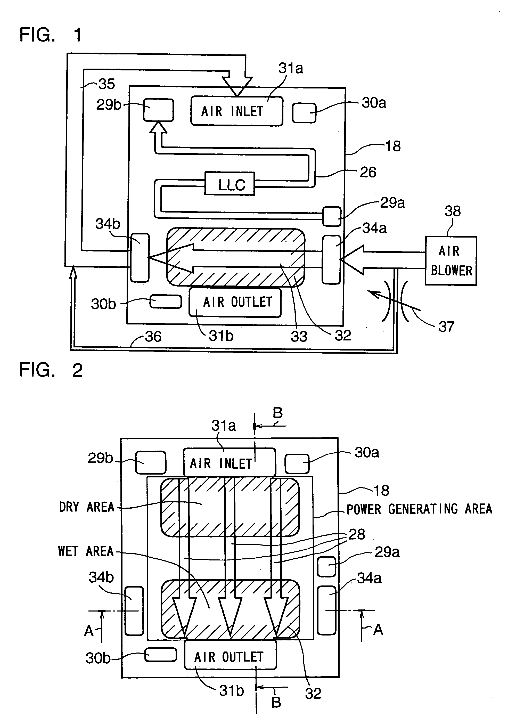
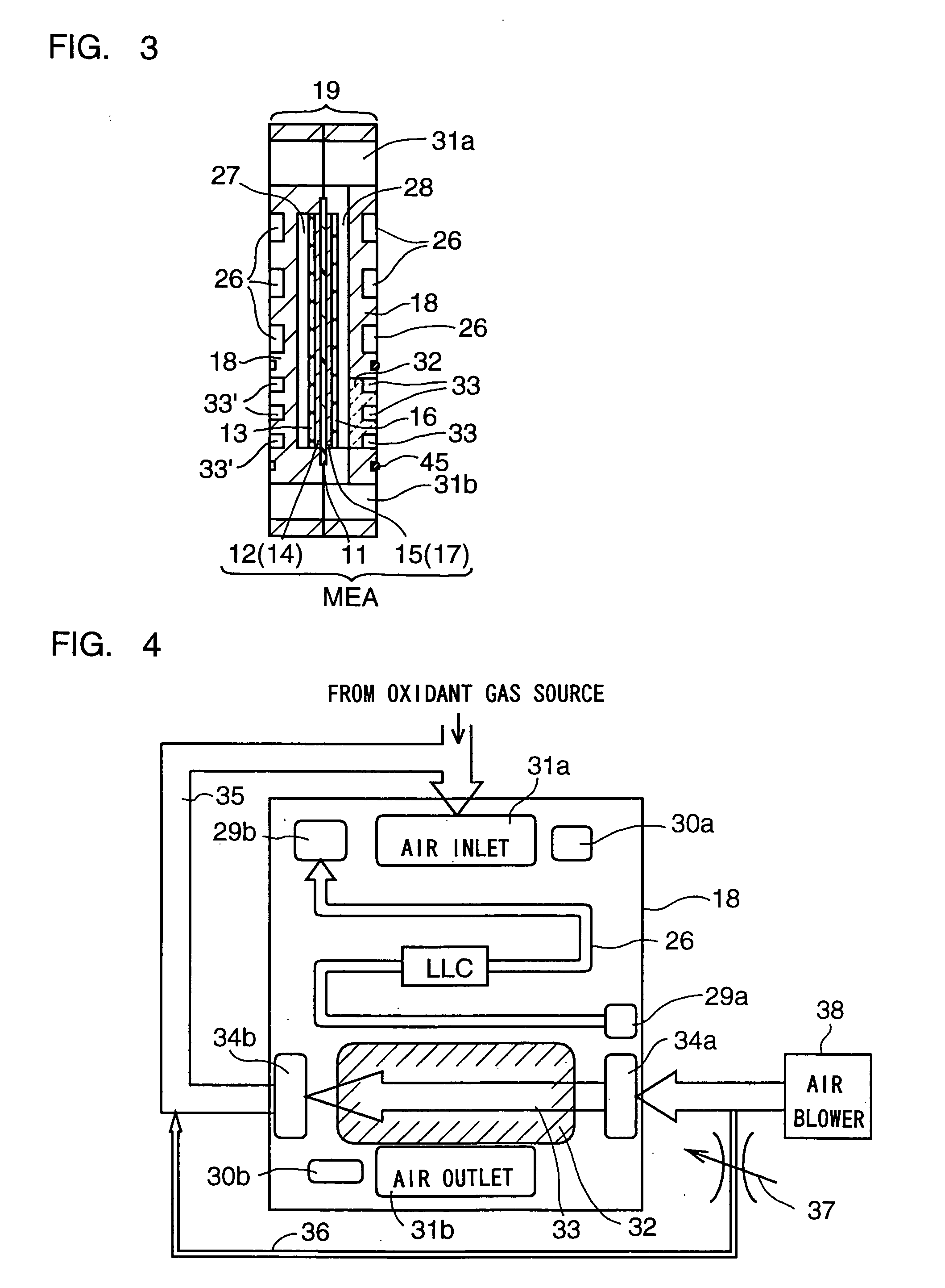
[0086] With embodiment 1 of the present invention, as is illustrated in FIGS. 1-4, the cooling gas passage 33 of the separator 18 is fluidly connected to a blower 38 on an upstream side of the cooling gas passage 33. A discharging port of the blower 38 is fluidly connected to the cooling gas supply manifold 34a, and an intake port of the blower 38 communicates with a cooling gas source (atmosphere). The cooling gas circuit communicates with the reactant gas supply passage 30a, 31a (into the oxidant gas supply manifold 31a) on the downstream-side of the cooling gas passage 33 via the connecting passage 35. No blower is provided in the connecting passage 35. The cooling gas is used for the reactant gas as it is. In FIG. 1, the cooling gas is air.

[0087] At a downstream portion of the reactant gas passage 27, 28 (the oxidant gas passage 2 in the illustrated example), a porous portion 32 is formed. At the MEA opposing surface of the porous portion 32, the reactant gas passage 27, 28 is f...

embodiment 2

[0089] With embodiment 2 of the present invention, as is illustrated in FIG. 5, a blower 38 is disposed in the connecting passage 35 which connects the cooling gas passage 33 and the reactant gas supply passage, on the downstream side of the cooling gas passage 33. A discharge port of the blower 38 is fluidly connected to the reactant gas supply manifold 30a, 31a, while an intake port of the blower 38 is fluidly connected to the cooling gas exhaust manifold 34b. The cooling gas circuit is connected to the reactant gas supply manifold 30a, 31a (the oxidant gas supply manifold 31a in the illustrated example) on the downstream side of the cooling gas passage 33, via the connecting passage 35 and the blower 38. No blower is provided on an upstream side of the cooling gas passage 33. The cooling gas is used as reactant gas as it is. In the example of FIG. 5, the cooling gas is air.

[0090] At a downstream portion of the reactant gas passage 27, 28 (the oxidant gas passage 28 in the illustr...

embodiment 4

[0095] With embodiment 4 of the present invention, as illustrated in FIG. 7, the porous portion 32 is formed in the anode-side separator 18. The fuel gas passage 27 is formed at one surface of the porous portion 32, and the cooling gas passage 33′ is formed at the other surface of the porous portion 32. Fuel gas (e.g., hydrogen) flows in the cooling gas passage 33′. In a cathode-side separator of an adjacent fuel cell, a cooling gas passage 33 is formed at a surface opposite to an MEA opposing surface where an oxidant gas passage 28 is formed, of the separator of the adjacent fuel cell. The cooling gas passage 33 of the adjacent fuel cell is not partitioned from the cooling gas passage 33′ of the instant fuel cell, and fuel gas (e.g., hydrogen) flows the cooling gas passage 33 of the adjacent fuel cell. In the cathode-side separator of the adjacent fuel cell, a separator portion between the oxidant gas passage 33 at one surface of the separator and the cooling gas passage 33 at the ...


PUM


Abstract

In a fuel cell, a porous portion is formed in a separator. At a surface of the porous portion opposite to a surface where a reactant gas passage is formed, a cooling gas passage is formed. The cooling gas passage may be fluidly connected to a reactant gas supply passage for supplying reactant gas to the fuel cell. The cooling gas passage is controllable in flow amount. The porous portion is formed only in a separator portion where a downstream portion of the reactant gas passage is located. At a separator portion where an upstream portion of the reactant gas passage is located, a coolant passage is formed. A rib and a rib-bottom portion have a great porosity. A groove may be filled with porous material. The porous portion may be replaced by a water exchange portion. A portion of the separator other than the region of the porous portion may be made by porous material. Due to these, a fuel cell can be obtained where removal of product water is improved, product water can be utilized for humidifying gas, and product water can be uniformly removed.

Description

FIELD OF THE INVENTION [0001] The present invention relates to a fuel cell. More particularly, the present invention relates to a PEFC (Polymer Electrolyte Fuel Cell) in which removal of product water is improved. BACKGROUND OF THE INVENTION [0002] The PEFC includes a layer of a membrane-electrode assembly (MEA) and a separator. The MEA includes an electrolyte membrane of an ion-exchange membrane and a pair of electrodes disposed on opposite sides of the membrane. The pair of electrodes includes an anode disposed on one side of the membrane and including a first catalyst layer and a cathode disposed on the other side of the membrane and including a second catalyst layer. The separator includes a fuel gas passage formed therein for supplying fuel gas (e.g., hydrogen) to the anode, or an oxidant gas passage for supplying oxidant gas (e.g., oxygen, usually, air) to the cathode, and / or a coolant passage formed therein for letting coolant (usually, cooling water) flow through the coolant...

Claims


Application Information

Patent Timeline
IPC IPC(8): H01M8/02H01M8/04H01M8/10
CPCH01M8/0228H01M8/023H01M8/0258H01M8/0267Y02E60/50H01M8/04074H01M8/04089H01M8/04156H01M8/04253H01M8/04014H01M8/026H01M8/0263H01M8/2483H01M8/02H01M8/04
Inventor SANO, SEIJIARAKI, YASUSHI
Owner TOYOTA JIDOSHA KK
Why Eureka
Try Eureka