Bubble column-type fischer-tropsch synthesis slurry bed reaction system

a slurry bed and reaction system technology, applied in furnace types, lighting and heating apparatuses, furnaces, etc., can solve the problems of complex operating system, deterioration of performance, and inability to avoid the occurrence of clogging of catalyst particles in the filter, so as to facilitate the maintenance and the synthesis of slurry bed. , the effect of easy monitoring of the circulation condition

Inactive Publication Date: 2009-09-03
INPEX CORP +4
View PDF10 Cites 16 Cited by
  • Summary
  • Abstract
  • Description
  • Claims
  • Application Information

AI Technical Summary

Benefits of technology

[0031]As a result, a bubble column-type slurry bed reaction apparatus can be provided that has a simple operating system that synthesizes liquid hydrocarbons by the Fischer-Tropsch synthesis reaction, and separates and derives catalysts and liquid hydrocarbon products from a slurry composed of gas, liquid and solid phases. Moreover, 99% or more of those catalyst particles introduced to the lower portion of a separation vessel from the upper portion of the bubble column-type slurry bed reactor can be circulated to the reactor by carrying out gravity separation (sedimen

Problems solved by technology

However, in the case of filtration separation in the main reactor as advocated in Patent Documents 3 and 4, since a filter is used for the filtration means for separating the catalyst and liquid hydrocarbon products from the slurry, the occurrence of clogging of catalyst particles in the filter cannot be avoided.
Consequently, the operating system involved in separation and derivation as well as the apparatus ends up being complex.
In addition, since the catalyst particles become powdered when clogging/removal is repeated, in addition to causing deterioration of performance, there was also the possibility of stable operation being difficult.
Moreover, a combination of coiled cooling tubes and downward tubes has been disclosed to ensure temperature uniformity in slurry reactors suitable for efficiently removing the heat of the reaction, and these serve to evenly remove heat in the direction of the vertical axis of the reactor, however resulting in greater complexity of the apparatus configuration.
Consequently, there is still the occurrence of problems accompanying clogging of the filter by catalyst particles.
In addition, although a slurry bed reactor is disclosed that. is suitable for efficiently remo

Method used


Image

  • Bubble column-type fischer-tropsch synthesis slurry bed reaction system
  • Bubble column-type fischer-tropsch synthesis slurry bed reaction system

Examples


example 1

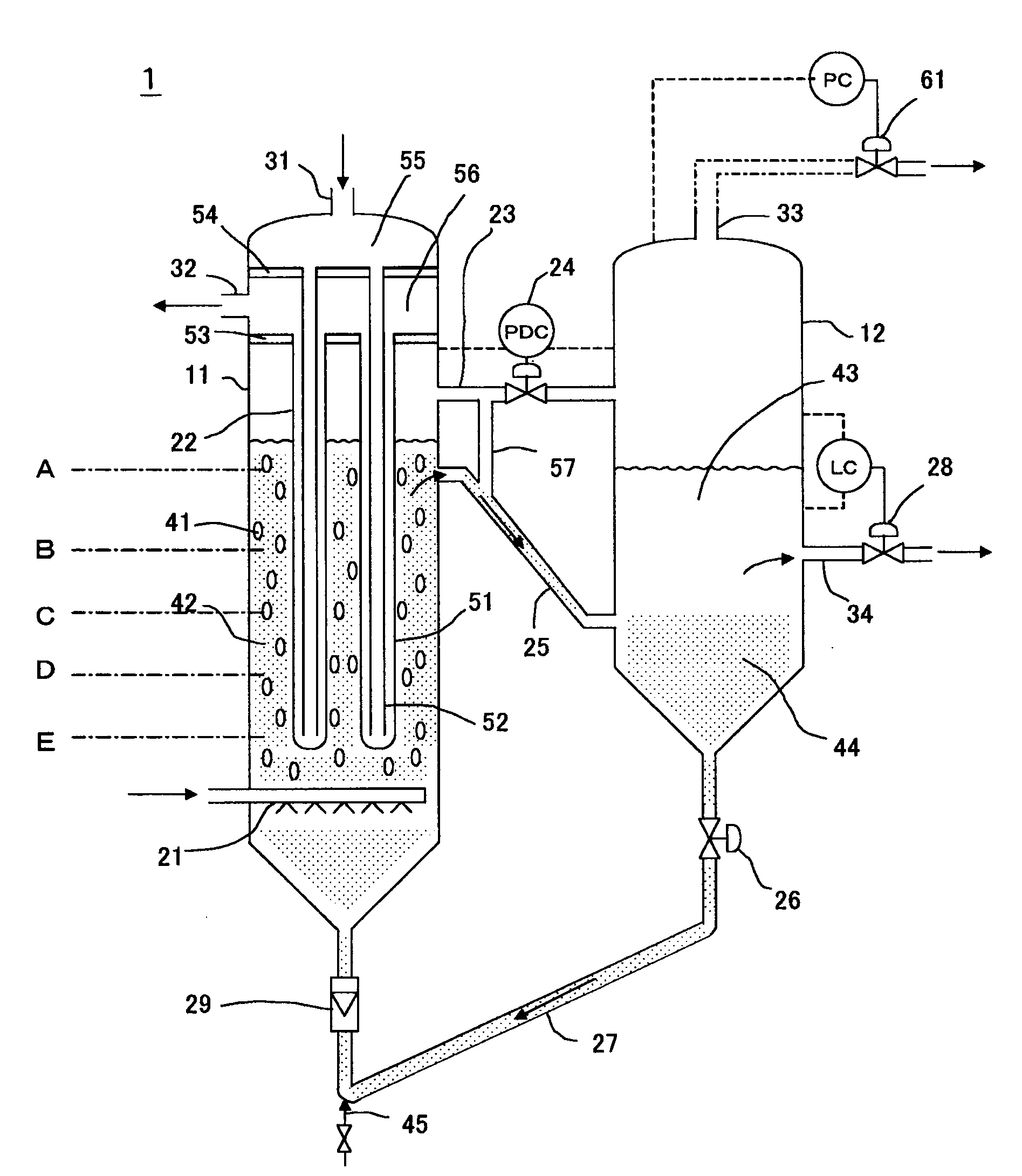
[0091]The reaction apparatus shown in FIG. 1 was used for the reaction apparatus.

[0092]Liquid hydrocarbon was produced by an FT synthesis reaction by supplying synthesis gas at a feed rate of 250 Nm3hour (100% load) and controlling the reaction pressure to be 2200 kPaG and the reaction temperature to be 240° C. (±2° C.). The results are shown in Table 1. In addition to controlling the reaction temperature inside the reactor to be in the aforementioned temperature range, boiler water was fed into the inner tubes of a plurality of bayonet-type cooling tubes, and controlled so as to obtain steam having a temperature of 231° C. and a pressure of 2735 kPaG from the cooling tube outer tube outlet. In addition, the CO conversion during this FT synthesis reaction was 62% under these operating conditions.

[0093]The temperature profile inside the reactor demonstrated a uniform temperature profile in which the temperature difference in the direction of the vertical axis of the reactor was 2° C....

example 2

[0094]A liquid hydrocarbon was produced by an FT synthesis reaction by supplying a synthesis gas at a feed rate of 100 Nm3hour (40% load) and controlling the reaction pressure to be 2200 kPaG and the reaction temperature to be 230° C. using the same reaction apparatus as in Example 1. The results are shown in Table 1. In addition to controlling the reaction temperature inside the reactor to be in the aforementioned temperature range, boiler water was fed into the inner tubes of a plurality of bayonet-type cooling tubes, and controlled so as to obtain steam having a temperature of 226° C. and a pressure of 2450 kPaG from the cooling tube outer tube outlet. In addition, the CO conversion during this FT synthesis reaction was 89% under these operating conditions. The temperature profile inside the reactor demonstrated a uniform temperature profile in which the temperature difference in the direction of the vertical axis of the reactor was 1° C. or less under the conditions of a superfi...


PUM


Abstract

A bubble column-type slurry bed reaction system is provided in which an operating system, which synthesizes liquid hydrocarbons by the Fischer-Tropsch (FT) synthesis reaction and separates and derives a catalyst and liquid hydrocarbon products from a slurry composed of gas, liquid and solid phases, can be simplified, and deterioration of catalyst particles caused by attrition and so forth can be reduced. In this FT synthesis reaction system, a bubble column-type slurry bed Fischer-Tropsch synthesis reaction process, in which synthesis gas supplied continuously from the bottom of a reactor and suspended catalyst particles are contacted to form liquid hydrocarbons, gaseous hydrocarbons and water, a process in which a slurry of suspended liquid products formed in the Fischer-Tropsch synthesis reaction process and catalyst particles moves from the reactor to the lower portion of a separation vessel through a downwardly inclined transfer pipe to separate the catalyst particles and gaseous products, a process in which the liquid products formed in the Fischer-Tropsch synthesis reaction process is sent to the separation vessel through a horizontal connecting pipe installed above the downwardly inclined transfer pipe and derived from its apex, a process in which liquid products are derived from the separation vessel, and a process in which a
slurry in which catalyst particles are concentrated is derived from the bottom of the separation vessel and circulated to the bottom of the reactor, are driven by the driving force of synthesis gas introduced from the bottom of the reactor and which rises through the slurry bed reactor without using an external drive power source for circulation, and the formed liquid hydrocarbon products, gaseous hydrocarbon products and water are separated and derived without using an external drive power source for separation.

Description

TECHNICAL FIELD[0001]The present invention relates to a bubble column-type slurry bed reaction system and apparatus that convert a synthesis gas composed of hydrogen and carbon monoxide to liquid hydrocarbons product in the presence of a suspended Fischer-Tropsch synthesis catalyst.BACKGROUND ART[0002]A Fischer-Tropsch synthesis reaction involves the reaction of a synthesis gas composed of hydrogen and carbon monoxide in the presence of a solid catalyst to yield a mixture of paraffin and olefin hydrocarbons having a comparatively wide molecular weight distribution. Liquid hydrocarbons in particular are attracting attention as a clean-burning automobile fuel.[0003]Fischer-Tropsch synthesis reactions are characterized as being extremely exothermic. For example, the calorific value per kg-mol of carbon monoxide in the following general formula (1) representing the synthesis of saturated hydrocarbons is about 40 Mcal.nCO+2nH2→-(CH2)n-+nH2O   (1)[0004]Thus, one of the most important fact...

Claims


Application Information

Patent Timeline
IPC IPC(8): B01J8/24
CPCB01J8/007B01J8/085B01J8/1818B01J8/22B01J8/228C10G2300/805B01J2208/00539B01J2208/0061C10G2/342C10G2300/4006B01J2208/00123C10G2/00C10G65/12
Inventor ONISHI, YASUHIROFUJIMOTO, KENICHIROIHARA, MASARUSUEHIRO, YOSHIFUMIMORITA, YASUMASAINABA, KIYOSHISHIMIZU, TOSHIOIWAMOTO, OSAMU
Owner INPEX CORP
Why Eureka
Try Eureka