Laser Based Visual Effect Device and System

Active Publication Date: 2017-08-10
ANDERSON TIMOTHY LEE +1
View PDF4 Cites 5 Cited by
  • Summary
  • Abstract
  • Description
  • Claims
  • Application Information

AI Technical Summary

Benefits of technology

The present invention relates to a display and control system that can move in preset patterns while lasers vary in intensity and color. The system can be controlled through a mobile application or a central control system. The system also allows guests to submit messages that will be communicated into earth orbit and beyond. The technical effect is an enhanced user experience through a unique and innovative display and control system.

Problems solved by technology

However, with proper planning, some venues may allow the LSC to move and point in different directions, where the LSC may not be allowed to point in a designated direction for safety concerns.

Method used


Image

  • Laser Based Visual Effect Device and System
  • Laser Based Visual Effect Device and System
  • Laser Based Visual Effect Device and System

Examples


Embodiment Construction

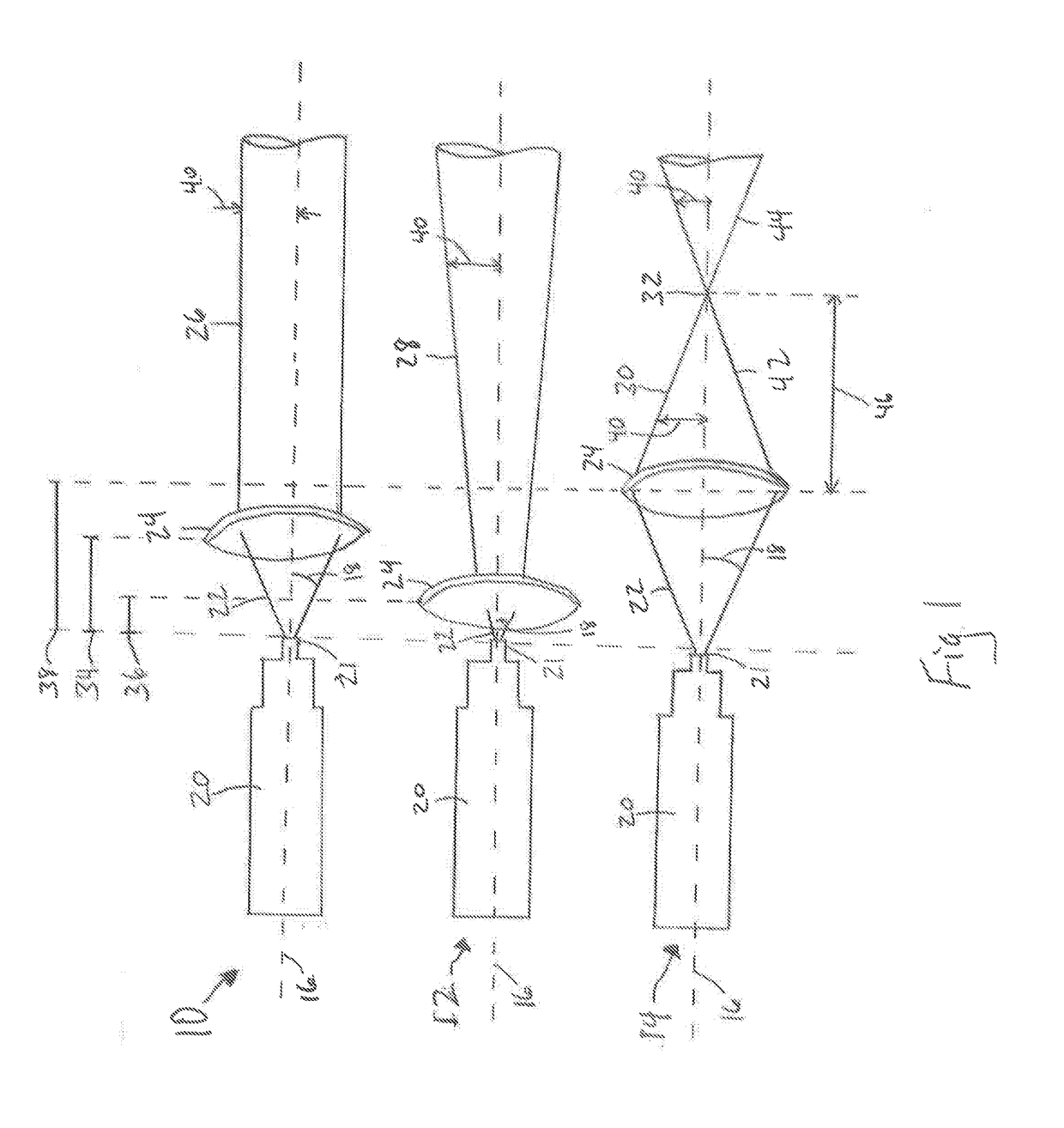
[0027]Referring initially to FIG. 1, three different laser configurations is shown. The first one is a collimating laser 10. Laser 10 comprises a laser body 20, out from which is raw laser beam 22 along central axis 16. Raw beam 22 exits laser body 20 at angle 18 from central axis 16. Raw laser beam 22 then passes through lens 24, which is located distance 34 from the laser output 21. Due to the effects of lens 24, lens 24 transforms raw laser beam 22 into collimated beam 26, where the outside of beam 26 maintains a constant distance 40 from central axis 16 along the length of beam 26.

[0028]Laser 12 is a diverging laser. Laser 12 consists of the same components as laser 10. However, in laser 12, lens 24 is a shorter distance 36 from laser output 21 of laser body 20 as compared to laser 10. The result of the shorter distance D2 on raw beam 22 is that beam exiting from lens 24 continually diverges further away from axis 16 as beam 28 gets further from lens 24. Put another way, distanc...


PUM


Abstract

Disclosed is a laser-based device for use primarily for laser light effects. The laser device comprises multiple red, green, and blue lasers. Each laser has a lens to collimate and focus each individual beam. The lasers are aligned such that each laser shares a common output axis. The intensity of each laser is adjustable thereby allowing the overall output color of the device to change. The overall output has over 16 million colors. Each laser-based device has a gimbal-like system to allow the devices change theft orientation. A remote control system allows for the control and synchronization of multiple devices. Multiple devices may connect to the remote control system using cables, wireless transceivers, or both. Multiple devices may be located in close proximity to create a more powerful overall output beam. The remote control system allows for viewer interaction through an application installed onto a personal communication device.

Description

RELATED APPLICATIONS[0001]This application claims the benefit of priority to the United States Provisional Patent Application for “Lase Based Visual Effect Device and System,” Ser. No. 62 / 291,597 filed on Feb. 5, 2016, and currently co-pending.FIELD OF THE INVENTION[0002]The present invention pertains generally to a display projection device for use in entertainment. More particularly, the present invention pertains to a laser based device for projecting a collimated laser consisting of a grouping of smaller laser devices. The Present invention is particularly, but not exclusively, useful as a device for projecting a large laser beam for use during an entertainment event or as a location identifier.BACKGROUND OF THE INVENTION[0003]For almost as long a visible-wavelength lasers have existed, artists have been inspired to create stunning visual displays. These visual displays vary from multicolor forms and images projected onto a surface to large columns of light. Some implementations...

Claims


Application Information

Patent Timeline
IPC IPC(8): F21S10/02G03B21/14F21V14/02G03B21/20
CPCF21S10/023G03B21/2033G03B21/2013G03B21/145F21Y2105/10F21V14/02G03B21/16F21Y2113/13F21V29/56G03B21/2093F21S2/00F21V14/06F21V21/30F21Y2115/30G03B21/20
Inventor ANDERSON, TIMOTHY LEEKOVACS, TAMAS
Owner ANDERSON TIMOTHY LEE
Why Eureka
Try Eureka