Laser amplifier

Inactive Publication Date: 2017-08-10
JGM ASSOC
View PDF5 Cites 8 Cited by
  • Summary
  • Abstract
  • Description
  • Claims
  • Application Information

AI Technical Summary

Benefits of technology

[0008]Limiting the “effective” gain bandwidth of the amplifier, as discussed below, can prevent ASE at undesired wavelengths outside the intended or desired wavelength range. Reduced gain bandwidths might also reduce unwant

Problems solved by technology

However, in some laser design situations, the gain bandwidth provided by Yb-doped and other broad-bandwidth materials can be too large.
The result can be spurious lasin

Method used


Image

  • Laser amplifier
  • Laser amplifier
  • Laser amplifier

Examples


Embodiment Construction

[0032]Aside from the preferred embodiment or embodiments disclosed below, this invention is capable of other embodiments and of being practiced or being carried out in various ways. Thus, it is to be understood that the invention is not limited in its application to the details of construction and the arrangements of components set forth in the following description or illustrated in the drawings. If only one embodiment is described herein, the claims hereof are not to be limited to that embodiment. Moreover, the claims hereof are not to be read restrictively unless there is clear and convincing evidence manifesting a certain exclusion, restriction, or disclaimer.

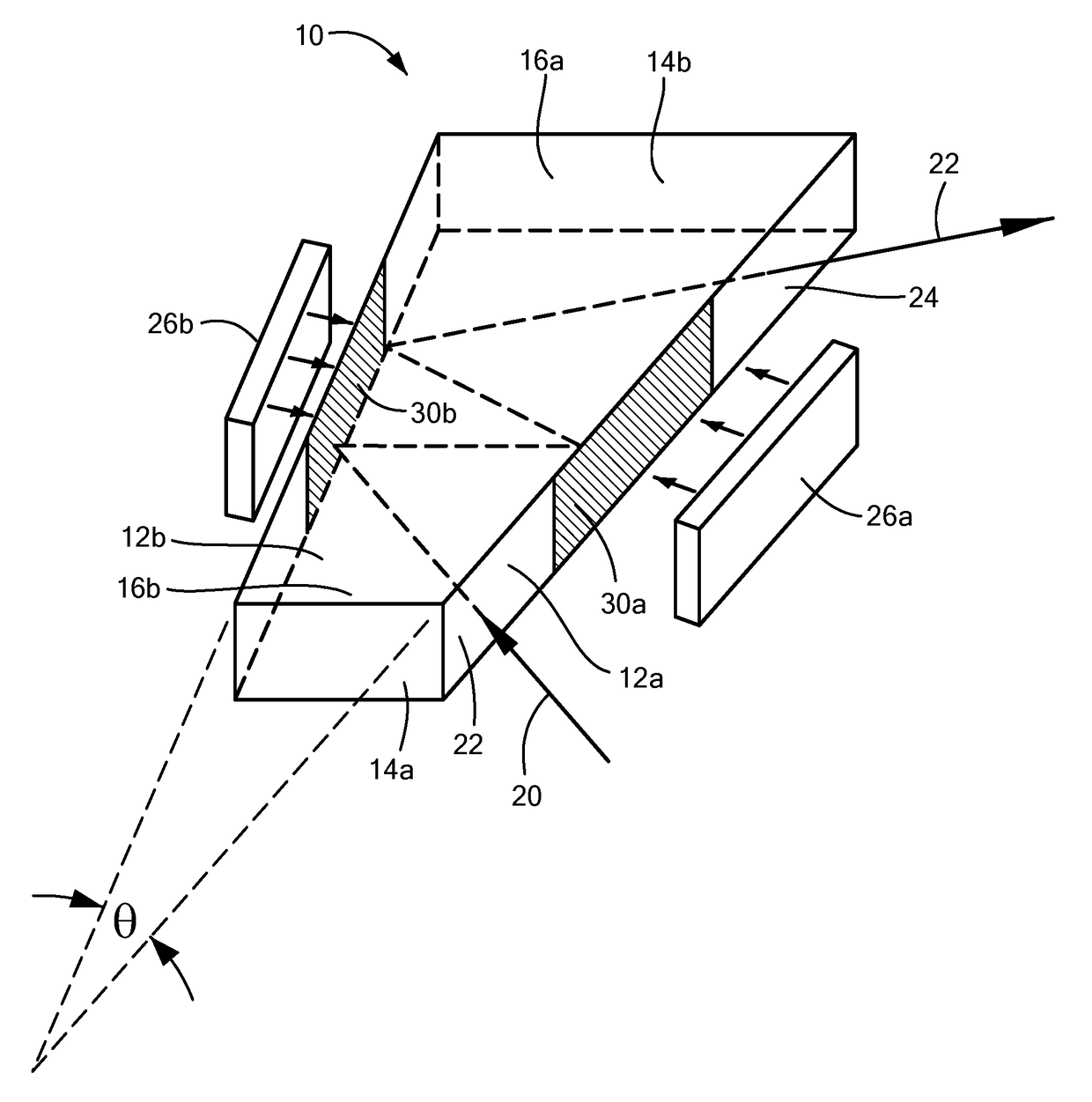
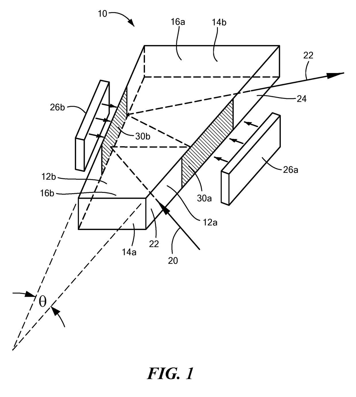
[0033]As shown in FIG. 1, broadband laser active or gain material slab 10 has a first lateral face 12a opposing the second space lateral face 12b with a wedge angle θ between faces 12a and 12b (exaggerated in FIG. 1). Slab 10 also includes opposing longitudinal faces 14a and 14b and opposing transverse faces 16a and 16b. Co...


PUM


Abstract

A laser amplifier includes a broadband laser gain medium having a first lateral face spaced from an opposing second lateral face at a wedge angle with respect to the first lateral face. At least the first lateral face receives a pump beam and one of the first and second lateral faces receives a seed beam. A first coating on the first lateral face is highly transmissive at the pump beam wavelength. A second coating is disposed on the second lateral face. In one example, the first coating is highly reflective at the seed beam wavelength over a first wavelength band and the second coating is highly reflective at the seed beam wavelength over a second wavelength band (partially or fully) overlapping the first wavelength band.

Description

RELATED APPLICATIONS[0001]This application claims benefit of and priority to U.S. Provisional Application Ser. No. 62 / 293,365 filed Feb. 10, 2016, under 35 U.S.C. §§119, 120, 363, 365, and 37 C.F.R. §1.55 and §1.78, which is incorporated herein by this reference.FIELD OF INVENTION[0002]The subject invention relates to laser amplifiers.BACKGROUND OF THE INVENTION[0003]A diode pumped laser amplifier typically includes a laser gain medium pumped by a diode laser beam or beams to amplify an incident or seed laser beam.[0004]In one design, a diode-pumped laser amplifier (“VHGM” amplifier) employs a zig-zag beam path through a wedged amplifier slab designed to suppress build-up of amplified spontaneous emission (ASE) that would otherwise act to prevent high laser gain. See U.S. Pat. No. 7,590,160 incorporated herein by this reference by the assignee hereof. The zig-zag path of the beam being amplified is configured by injecting the seed beam into the amplifier slab so it makes multiple bo...

Claims


Application Information

Patent Timeline
IPC IPC(8): H01S3/08H01S3/0941H01S3/16H01S3/06
CPCH01S3/08095H01S3/0625H01S2301/02H01S3/0606H01S3/1618H01S3/0941H01S3/2308
Inventor MANNI, JEFFREY G.
Owner JGM ASSOC
Why Eureka
Try Eureka