
Eureka
For R&D, Eureka makes reading and utilizing patents & technical documents easy.
Eureka AIR
Designed for self-driven R&D workflows. Generate viable solutions, solve complex R&D challenges, empower your innovation with AI.

Eureka Materials
Designed for material experts only. Revolutionize your material R&D, from search, analyze, to developing new materials.

TechResearch
Generate reliable direction feasibility study reports for your R&D in just a few steps.

TechSeek
Discover and master advanced knowledge NOW. Basics, ideas, possibilities, all at once.

TechMind
As an expert in R&D Theories, TechMind can generates customized viable solutions instantly.

TechRisk
Analyze your overall solution with one click, know your potential R&D risks in advance.

TechMonitor
Get weekly tech updates, stay abreast of the latest tech innovations and key insights.
Lighting device and lighting equipment
- Summary
- Abstract
- Description
- Claims
- Application Information
AI Technical Summary
Benefits of technology
Problems solved by technology
Method used
Image

Examples
embodiment 1
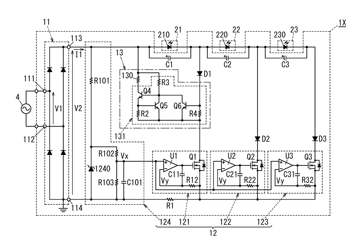
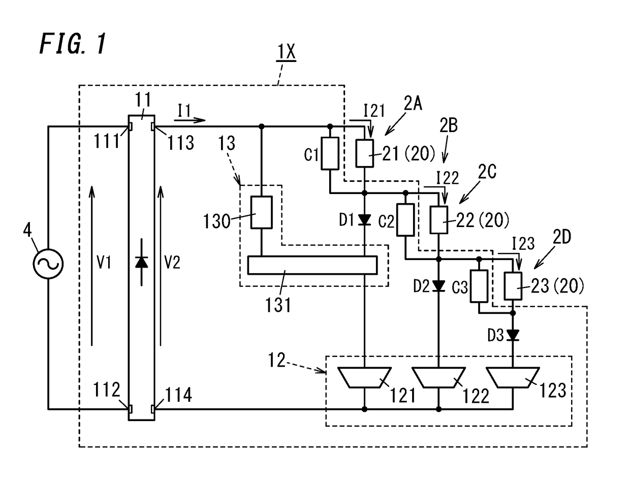
[0022]The present embodiment is explained with reference to FIG. 1. Note that in the example of FIG. 1, a lighting device 1X includes three solid light sources 20, but a lighting device of the present embodiment is not limited to this. For example, the lighting device of the embodiment may include two solid light sources 20, or four or more solid light sources 20. In short, the lighting device of the embodiment includes solid light sources 20. Each of the solid light sources 20 may be a solid light source array composed of LEDs (light emitting diodes). Each of the solid light sources 20 may be also electrically connected in parallel with a capacitor.
[0023]The lighting device of the embodiment includes a rectifier circuit 11, a driver circuit 12 and a shunt circuit 13. The rectifier circuit 11 includes a first polarity output terminal 113 and a second polarity output terminal 114 and that is configured to output, from the first polarity and second polarity output terminals 113 and 11...
embodiment 2
[0076]FIG. 8 shows a circuit configuration of a lighting device 1Y according to Embodiment 2. Note that since the circuit configuration of the lighting device 1Y is mostly common to the circuit configuration of the lighting device 1X shown in FIG. 4, identical constituent elements to those of the lighting device 1X have been allocated identical reference numerals, and description thereof has been omitted as appropriate.
[0077]The lighting device 1Y differs from the lighting device 1X in that it includes an integrated circuit (a first integrated circuit 30) as second and third constant current circuits, and a circuit (a shut-down circuit) configured to forcibly deactivate a first constant current circuit 121. The lighting device 1Y also differs from the lighting device 1X in that a shunt circuit 13 includes a control circuit 131 as shown in FIG. 7.
[0078]The first integrated circuit 30 includes transistors Q2 and Q3, a controller 300 configured to control the transistors Q2 and Q3, fir...
embodiment 3
[0086]Hereinafter, lighting equipment according to Embodiment 3 will be explained in detail.
[0087]FIG. 10A is a perspective view of lighting equipment 5A according to the embodiment.
[0088]The lighting equipment 5A includes a lighting device of the aforementioned lighting devices 1X, 1Y and 1Z, and a body 50A that houses the lighting device.
[0089]The lighting equipment 5A is, for example a down light configured to be recessed into a ceiling. The lighting equipment 5A includes: the body 50 A that houses first, second and third solid light sources 21, 22 and 23 and the lighting device; and a reflector 61. The body 50 A includes a heat sink 62 with radiation fins in an upper part thereof. The lighting equipment 5A further includes a power cord 63 fixed from the body 50A. The power cord 63 is used to electrically connect the lighting device in the body 50A and an AC power supply 4.
[0090]The lighting equipment is not limited to the down light, but may be another type of lighting equipment...
PUM
 Abstract
Description
Claims
Application Information
 - R&D Engineer
- R&D Manager
- IP Professional
- Industry Leading Data Capabilities
- Powerful AI technology
- Patent DNA Extraction
Browse by: Latest US Patents, China's latest patents, Technical Efficacy Thesaurus, Application Domain, Technology Topic, Popular Technical Reports.
© 2024 PatSnap. All rights reserved.Legal|Privacy policy|Modern Slavery Act Transparency Statement|Sitemap|About US| Contact US: help@patsnap.com