This helps you quickly interpret patents by identifying the three key elements:
Problems solved by technology
Method used
Benefits of technology
Benefits of technology
The patent describes a medical instrument assembly that allows for easy attachment and detachment of a tracking sensor to different types of medical instruments. This is achieved through an attachment device that can be adjusted to connect the tracking sensor to the instrument. This design can be used with multiple types of medical instruments, reducing the cost and complexity of the electromagnetic tracking system. The technical effect of this invention is improved efficiency and flexibility in surgical navigation procedures.
Problems solved by technology
However, in examples where the first coil assembly is coupled to the medical instrument, it may take a significant amount of time to identify and calibrate the receiver for the specific instrument being used.
Such constrains require multiple different coil assembly designs which increases manufacturing costs.
In other examples, where the coil assembly is included within the medical instrument, the cost of the medical instrument is increased, and the lifespan of coil assembly is reduced (e.g., may be limited to a one-time use).
Method used
Image
Click on the blue label to locate the original text in one second.
Reading with bidirectional positioning of images and text.
Examples
first embodiment
[0118]Turning now to FIGS. 5-9, they show examples of the medical instrument assembly, where the first mating interface of the handle of the medical instrument includes the attachment device.
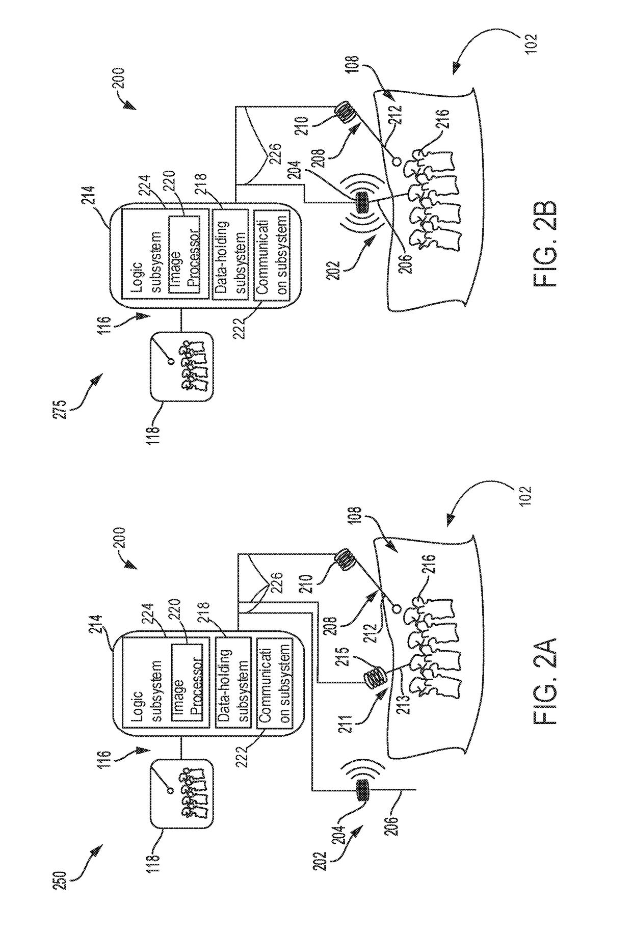
[0119]Focusing on FIG. 5, it shows an exterior side perspective view 500 of an example tracking sensor 502 (e.g., tracking sensor 210 described above in FIGS. 2A and 2B). Thus, tracking sensor 502 may be the same or similar to tracking sensor 210 described above with reference to FIGS. 2A and 2B. As such, tracking sensor 502 may be included in the electromagnetic surgical navigation system (e.g., electromagnetic tracking system 200 shown in FIGS. 2A and 2B).
[0120]Tracking sensor 502 comprises a housing 504 that encloses interior components of the tracking sensor 502, which will described in greater detail below with reference to FIG. 6. The housing 504 may include six walls: top wall 506, bottom wall 508, first side wall 510, second side wall 512, front wall 514, and back wall 516. The walls 506...
second embodiment
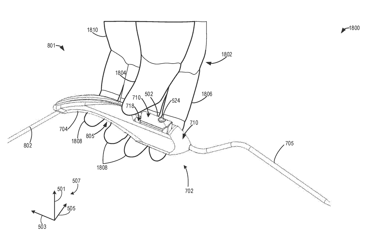
[0178]FIG. 12 shows an isometric view 1200 of the medical instrument assembly 801 described above in FIG. 11, where the tracking sensor 502 is physically coupled to the medical instrument 702.
third embodiment
[0179]Turning now to FIGS. 13-15, they show examples of the medical instrument assembly 801, where portions of the attachment device may be included on both the tracking sensor 502 and medical instrument 702. Focusing now on FIG. 13 it shows an embodiment of the tracking sensor 502, where the sensor 502 includes overhangs 1302, that may be formed on the corners of housing 504, where the bottom wall 508 and second side wall 512, meet with one of the front wall 514 and back wall 516. Thus, in the example shown in FIG. 13 two overhangs 1302 may be included, although only one is depicted in FIG. 13. However, it should be appreciated that the positioning of the overhangs 1302, and number of overhangs 1302 may be adjusted as desired.
[0180]The overhangs 1302 may extend from the walls 514 and 516, below the bottom wall 508, along edges of the bottom wall 508. Thus, the overhangs 1302 may be flush with, and parallel to the front wall 514 and back wall 516. The overhangs 1302 may include aper...
PUM
Abstract
Methods and systems are provided for an electromagnetic coilassembly for a surgical navigation tracking system which may be used during image-guided surgery. A medical instrument assembly for an electromagnetic surgical navigation system, may comprise a tracking sensor interface included within a handle of a medical instrument, the interface having a first mating surface. Further, the assembly may include a tracking sensor including a second mating surface and one or more electromagnetic coils, where the tracking sensor is removably coupled to the tracking sensor interface of the medical instrument via an attachment device included on one or more of the first mating surface and second mating surface.
Description
FIELD[0001]Embodiments of the subject matter disclosed herein relate to an electromagnetic trackingsystem, and more particularly, to an electromagnetic trackingsystem for use in image-guided surgery.BACKGROUND[0002]Electromagnetic tracking systems have been used in various industries such as aviation, motion sensing, retail, and medicine to provide position and orientation information for objects. They employ electromagnetic coils as electromagnetic transmitters and receivers. The electromagnetic field generated by the transmitter may be sensed by the receiver and used to estimate a position and / or orientation of the receiver relative to the transmitter.[0003]In medical applications, electromagnetic tracking systems have proven particularly useful because they can track medical instruments such as catheters and needle tips within a patient's body, without line-of-sight requirements. Thus, when a medical instrument is obscured from view, such as when it is inserted into a patient's...
Claims
Application Information
Patent Timeline
Application Date:The date an application was filed.
Publication Date:The date a patent or application was officially published.
First Publication Date:The earliest publication date of a patent with the same application number.
Issue Date:Publication date of the patent grant document.
PCT Entry Date:The Entry date of PCT National Phase.
Estimated Expiry Date:The statutory expiry date of a patent right according to the Patent Law, and it is the longest term of protection that the patent right can achieve without the termination of the patent right due to other reasons(Term extension factor has been taken into account ).
Invalid Date:Actual expiry date is based on effective date or publication date of legal transaction data of invalid patent.

