
On-the-fly redundancy operation for forming redundant drive data and reconstructing missing data as data transferred between buffer memory and disk drives during write and read operation respectively

a technology of redundant drive and write and read operation, applied in the field of digital data storage, can solve the problems of sharp drop in reliability, limited system performance, and inability to keep up with the speed of disk drive technology, so as to reduce the cost and complexity of disk array controller apparatus, improve disk array performance, and improve disk array performance

Inactive Publication Date: 2006-12-05
NVIDIA CORP
View PDF26 Cites 20 Cited by
  • Summary
  • Abstract
  • Description
  • Claims
  • Application Information

AI Technical Summary

Benefits of technology

[0022]In view of the foregoing background, the need remains to improve disk array performance. It is an object of the present invention to provide improved disk array performance while reducing the cost and complexity of disk array controller apparatus. Another object of the invention is to reduce delays associated with handling redundant data in a RAID system. In the best case, there should be no performance penalty resulting from applying redundancy to improve disk array storage reliability. Important aspects of the invention include the following:1. SYNCHRONOUS DATA TRANSFER
[0024]In one illustrative embodiment of the invention, it is applied to an array of N IDE drives. The data stripe is two bytes wide, the width of the IDE bus. The buffer memory width of the controller is 2×N bytes wide, the combined width of the IDE interfaces of the active drives. To execute a read operation, for example, a single, global read command comprising the starting sector number, the number of sectors to be read, and a “read sector” command type is “broadcast” to all of the drives at once. This information is written to a “command block” of registers in each IDE drive. Since data preferably is striped identically to all drives, the read command information is the same for all drives. This feature enhances performance by eliminating the time required to send commands to all of the drives sequentially. Writing to the command block of registers starts processing of the command in the drives.
[0028]In a disk write operation, data is first moved into the ring from the RAM buffer, by shifting the data around the ring until the ring is “loaded” with write data. For example, four 16-bit latches are loaded with a total 8-byte word. Then the ring data is transferred in parallel (“broadside”) into the latching transceivers. The latching transceivers hold the data stable while it is copied into the drives in response to a write strobe. While the first 8-byte word is written to the drives (two bytes to each drive), the ring is loaded with the next 8-byte word of write data. In a read operation, a common read command is broadcast to all of the drives. When all of the drives are ready, data is transferred into all of the latching transceivers from all of the drives in parallel. Next the data is transferred, again in parallel, from the latching transceivers into the ring of latches. Finally, the data is stored in the RAM buffer by shifting it around the ring until the last byte pair is presented at the output of the ring latch coupled to the RAM buffer port. While that first 8-byte word of read data is transferring into the RAM, the next word of data is being transferred from the drives into the latching transceivers. These steps are repeated until the disk access requested by the host is completed. The ring structure has numerous advantages, including eliminating the need to synthesize staggered strobes, and providing disk array access operations using essentially only three control signals—a common disk strobe, a common transfer strobe, and a common ring clock—regardless of the number of disk drives in the array.
[0032]To reconstruct missing data in the event of any single drive failure, the serialized read data stream is passed through an N+1 stage pipeline register. To begin, a word from the first drive is loaded into an accumulator and into the pipeline. As the next data word enters the pipeline from the next drive, it is XORed with the first word and the result stored in an accumulator. This process is repeated for each subsequent drive except that data from the failed drive is ignored. Once the data from the last (redundant) drive enters the pipeline, the accumulator will be holding the data from the missing drive. This result is transferred to a hold latch, and when the missing word in the pipeline from the failed drive is reached, the contents of the hold latch is substituted in place of the pipeline contents. A disk read with one drive failed is performed in a single pass of the data and without any performance penalty. Thus the drive failure is essentially transparent to the host, although it can be detected and logged for repair at a convenient time. Circuitry for forming redundant data, and circuitry for reconstructing missing data, can be conveniently inserted into the word-serial data stream on the disk drive side of the RAM buffer. A disk array controller as described herein preferably is implemented as an Application Specific Integrated Circuit ASIC for low cost volume production.

Problems solved by technology

Disk drive technology has not kept up, however.
Unfortunately, increasing the RPM much above 5000 causes a sharp drop off in reliability.
System performance thus is limited because the faster microprocessor is hampered by the disk drive data transfer “bottleneck”.
Such a local buffer does not provide any advantage for a single random access (other than making the disk and host transfer rates independent).
Despite all of the prior art in disk drives, controllers, and system level caches, a process cannot average a higher disk transfer rate than the data rate at the head.
Unfortunately, this approach is not directly applicable to disk drives.
Disk arrays require substantial supporting hardware, however.
While four drives have the potential of achieving four times the single drive transfer rate, this would rarely be achieved if the disk capacity were simply mapped consecutively over the four drives.
A single drive failure rate which previously might have been adequate becomes unacceptable in an array.
Redundancy in known RAID systems, however, exacts penalties in performance and complexity.
IDE drives dominate the low end of the market in terms of cost, capacity, and performance.
Because of these random accesses to the RAM buffer, it is impossible to take advantage of DRAM page mode operation which would otherwise offer higher bandwidth at lower memory cost.
For these reasons, known N-channel DMA controllers are relatively large, complex and expensive devices.
The size and complexity of RAID controllers are aggravated by redundancy requirements.
If surplus bandwidth is not available, the generation of redundant write data slows the write process considerably.
This is rationalized as an appropriate solution in some applications since writes occur much less often than reads so that the impact on overall disk performance is much less than a factor of two, but there is a performance penalty in prior art to provide redundancy.
Moreover, in the event of a read error or a single drive failure, a second pass through read data in the buffer is again required to reconstruct and restore the missing data.
And due to data striping, a given record requested by the host cannot be returned until the last drive has completed its access.
Additionally, in the prior art, redundancy requires either increased cost for higher bandwidth memory or reduced performance.

Method used


Image

  • On-the-fly redundancy operation for forming redundant drive data and reconstructing missing data as data transferred between buffer memory and disk drives during write and read operation respectively
  • On-the-fly redundancy operation for forming redundant drive data and reconstructing missing data as data transferred between buffer memory and disk drives during write and read operation respectively
  • On-the-fly redundancy operation for forming redundant drive data and reconstructing missing data as data transferred between buffer memory and disk drives during write and read operation respectively

Examples


Embodiment Construction

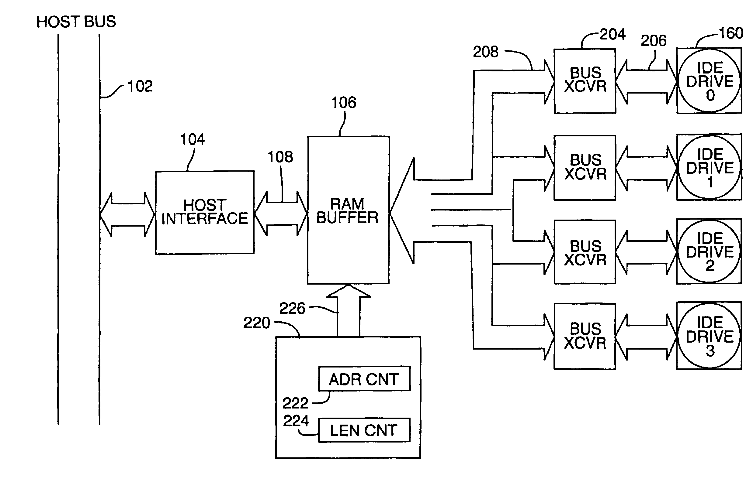
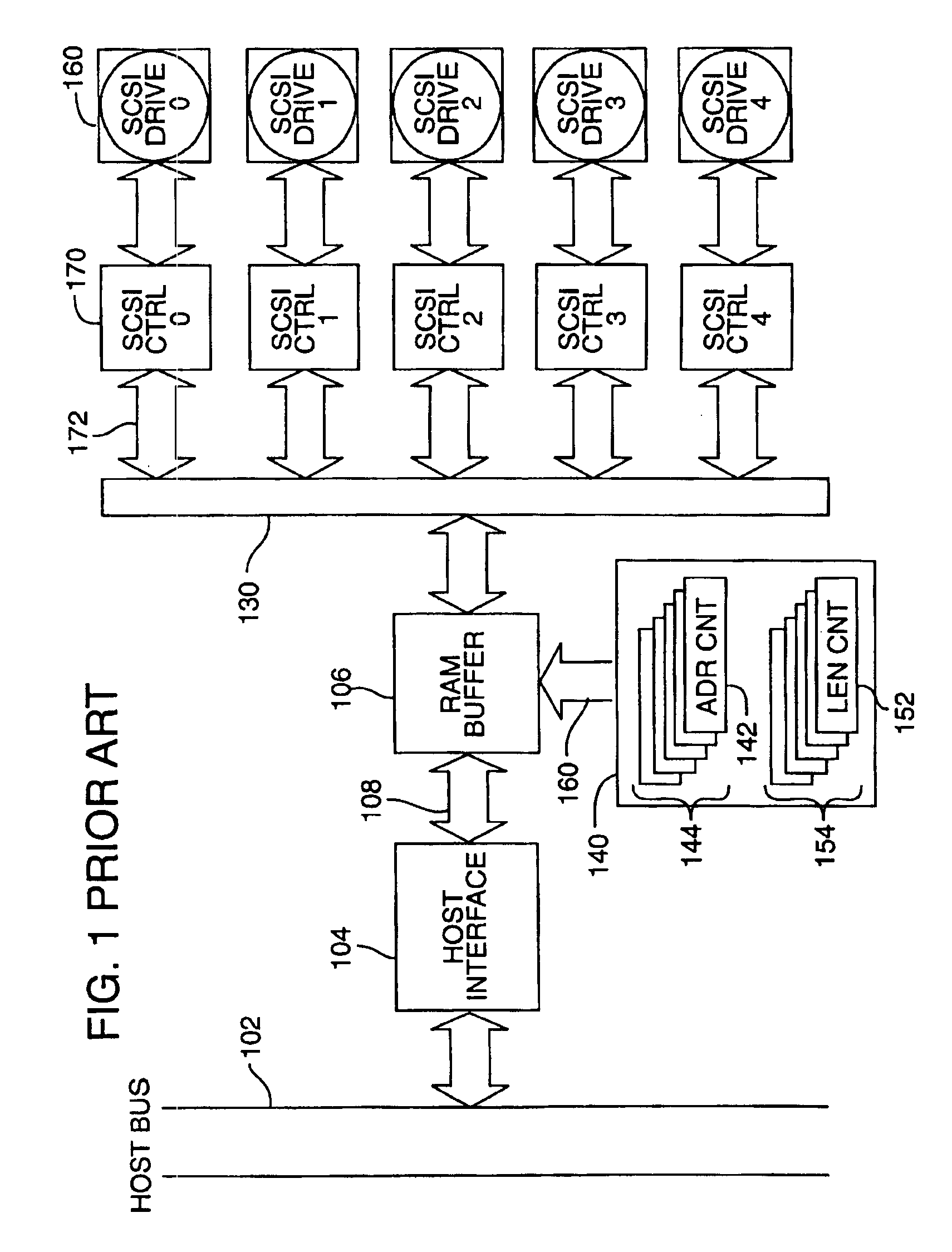
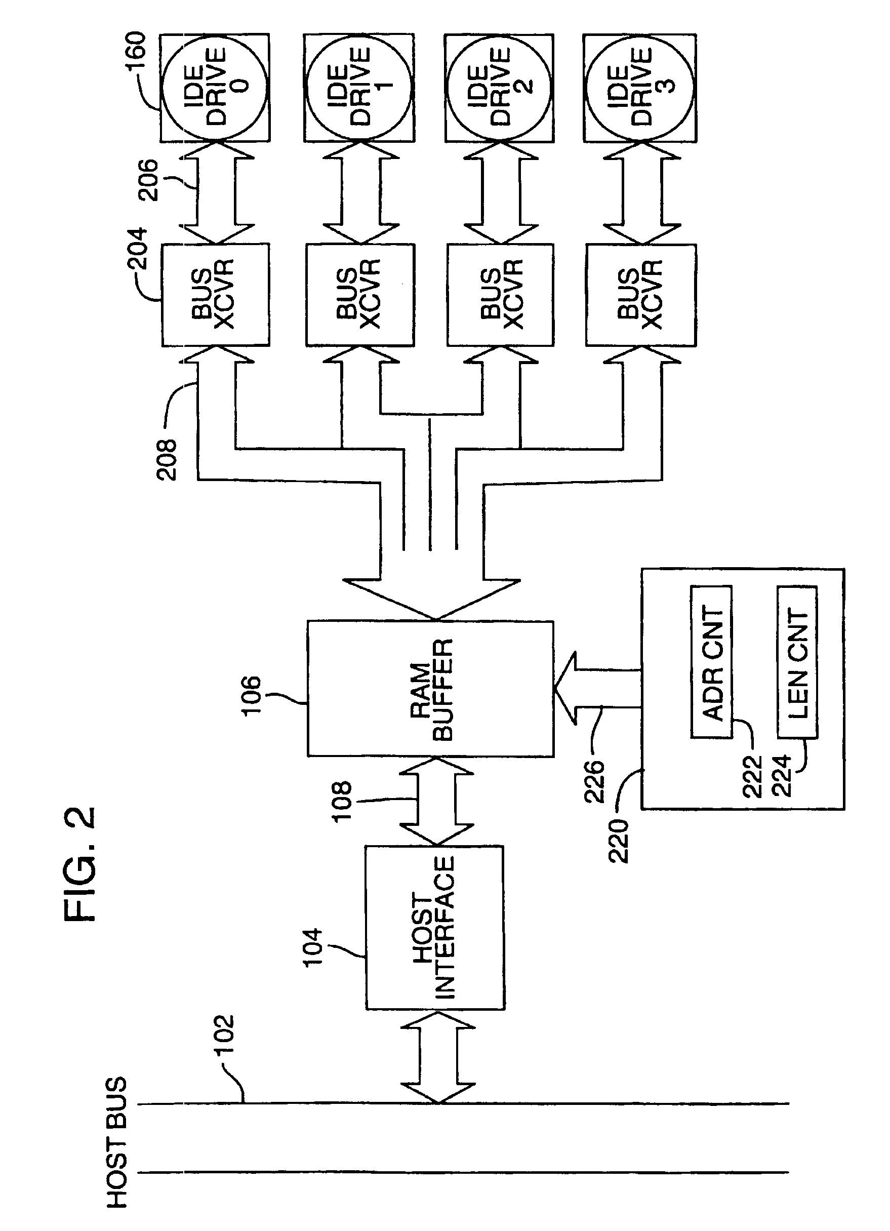
[0049]FIG. 2 is a hardware block diagram illustrating one embodiment of the invention as applied to an array of IDE drives (0-3) so as to provide synchronous data transfer. The host bus 102, host interface 104 and RAM buffer 106 (also referred to herein as the “buffer memory” or “cache”) were described with reference to FIG. 1 previously. In the system of FIG. 2, each of the disk drives, IDE drive 0 through IDE drive 3, is coupled to the RAM buffer 106 through a respective bus transceiver circuit having the same width as the drive interface (for example 16 bits or 2 bytes). For example, drive 0 is coupled to bus transceiver (“BUS XCVR”) 204 via path 206 and bus transceiver 204 in turn is coupled via path 208 to the RAM buffer 106.

[0050]Support of the drive interfaces requires two types of information transfers, control and data. The data paths are shown in FIG. 2 as described. The control information shares 206—the drive data port, but does not come from the RAM. Another path, not s...


PUM


Abstract

A disk drive array controller and method carries out disk drive data transfers not only concurrently but also synchronously with respect to all of the drives in the array. For synchronous operation, only a single-channel DMA is required to manage the buffer memory. A single, common strobe is coupled to all of the drives for synchronous read and write operations, thereby reducing controller complexity and pin count. A ring-structure drive data bus together with double buffering techniques allows use of a single, common shift clock instead of a series of staggered strobes as required in prior art for multiplexing / demultiplexing buffer memory data, again providing for reduced controller complexity and pin count in a preferred integrated circuit embodiment of the new disk array controller. Methods and circuitry also are disclosed for generating and storing redundant data (e.g. “check” or parity data) “on the fly” during a write operation to a RAID array. Techniques also are disclosed for reconstructing and inserting missing data into a read data streamon the fly” so that a disk drive failure is transparent to the host.

Description

RELATED APPLICATION[0001]This is a division of application Ser. No. 08 / 642,453, filed May 3, 1996, now U.S. Pat. No. 6,018,778.TECHNICAL FIELD[0002]The present invention lies in the field of digital data storage and more specifically is concerned with disk drive controllers for multiple disk drives, generally known as disk drive arrays.BACKGROUND OF THE INVENTIONHard Disk Drives[0003]Hard disk drives are found today in virtually every computer (except perhaps low-end computers attached to a network server, in which case the network server includes one or more drives). A hard disk drive typically comprises one or more rotating disks or “platters” carrying a magnetic media on which digital data can be stored (or “written”) and later read back when needed. Rotating magnetic (or optical) media disks are known for high capacity, low cost storage of digital data. Each platter typically contains a multiplicity of concentric data track locations, each capable of storing useful information. ...

Claims


Application Information

Patent Timeline
IPC IPC(8): G06F13/14G06F3/06G06F11/10
CPCG06F3/061G06F3/0626G06F3/0656G06F3/0689G06F11/1076G06F2211/1054
Inventor STOLOWITZ, MICHAEL C.
Owner NVIDIA CORP
Learn More