
Fuel cell vehicle

a fuel cell and vehicle technology, applied in the direction of battery/cell propulsion, electric propulsion mounting, transportation and packaging, etc., can solve the problems of increasing the surface pressure applied from the tank, affecting the power transfer distance, and affecting the safety of the vehicle, so as to reduce the size of the driving mechanism, shorten the distance over which the power is transferred, and reduce the possibility

Active Publication Date: 2017-08-24
TOYOTA JIDOSHA KK
View PDF2 Cites 3 Cited by
  • Summary
  • Abstract
  • Description
  • Claims
  • Application Information

AI Technical Summary

Benefits of technology

The patent provides a solution to prevent damage to the pressure-reducing valve in fuel cell vehicles that can occur when there is a collision. The solution involves reducing the distance between the pressure-reducing valve and the tanks, which can decrease the risk of damage during a collision. Overall, this patent aims to make fuel cell vehicles safer and reliable.

Problems solved by technology

Because the high-pressure pipe needs to have a high strength, the high-pressure pipe is large in volume and involves a high cost.
In this case, in the event of a frontal collision or a rear-end collision of a vehicle, the pressure-reducing valve may he damaged due to an impact.
In particular, when the tanks are disposed such that the longitudinal direction of the tanks coincides with the vehicle front-rear direction, the surface pressure applied from the tanks increases, and thus the possibility that the pressure-reducing valve will be damaged increases.

Method used


Image

  • Fuel cell vehicle
  • Fuel cell vehicle
  • Fuel cell vehicle

Examples


Embodiment Construction

[0031]Hereinafter, the configuration of a fuel cell vehicle according to an example embodiment of the disclosure will be described in detail with reference to the accompanying drawings.

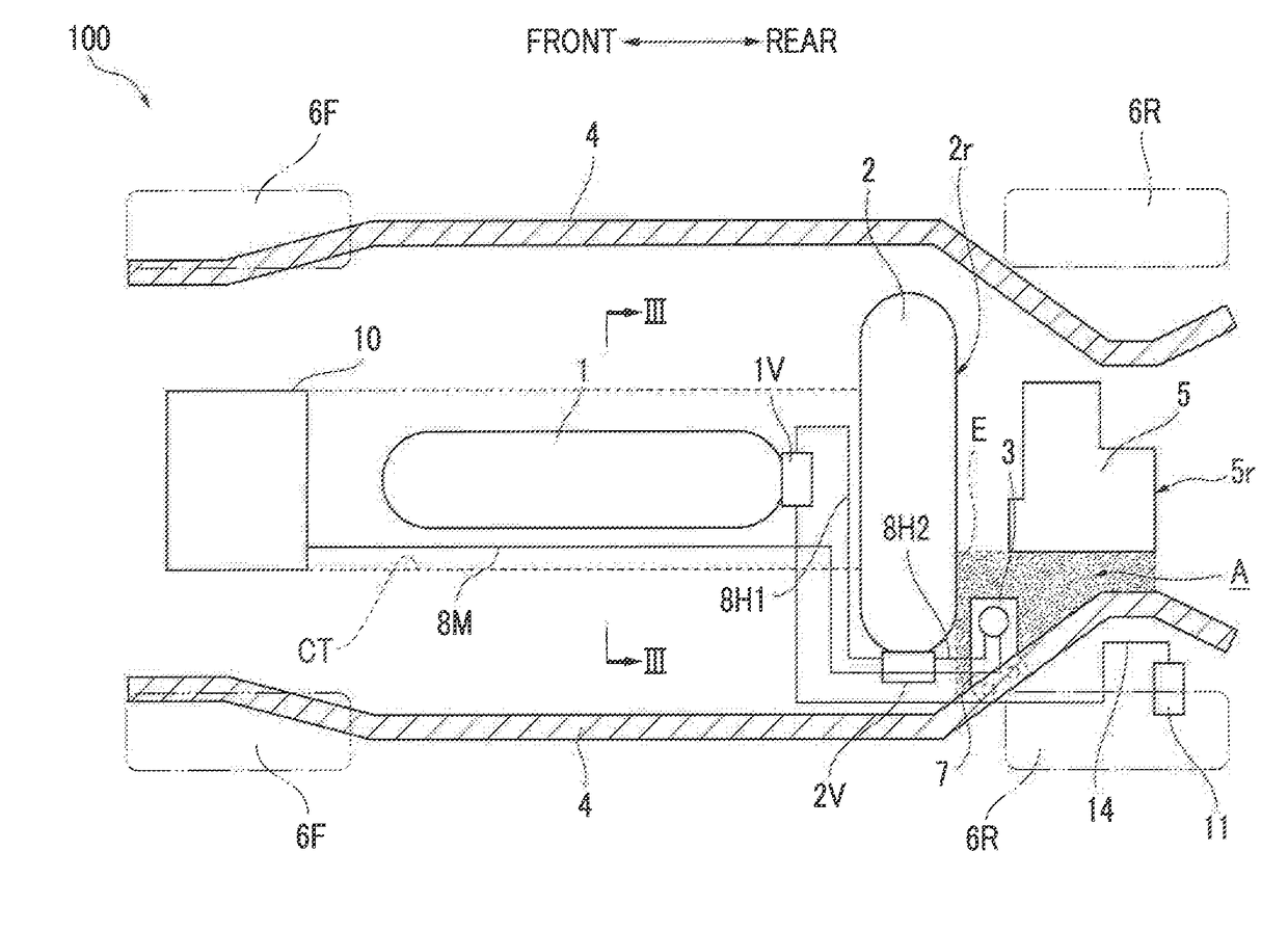
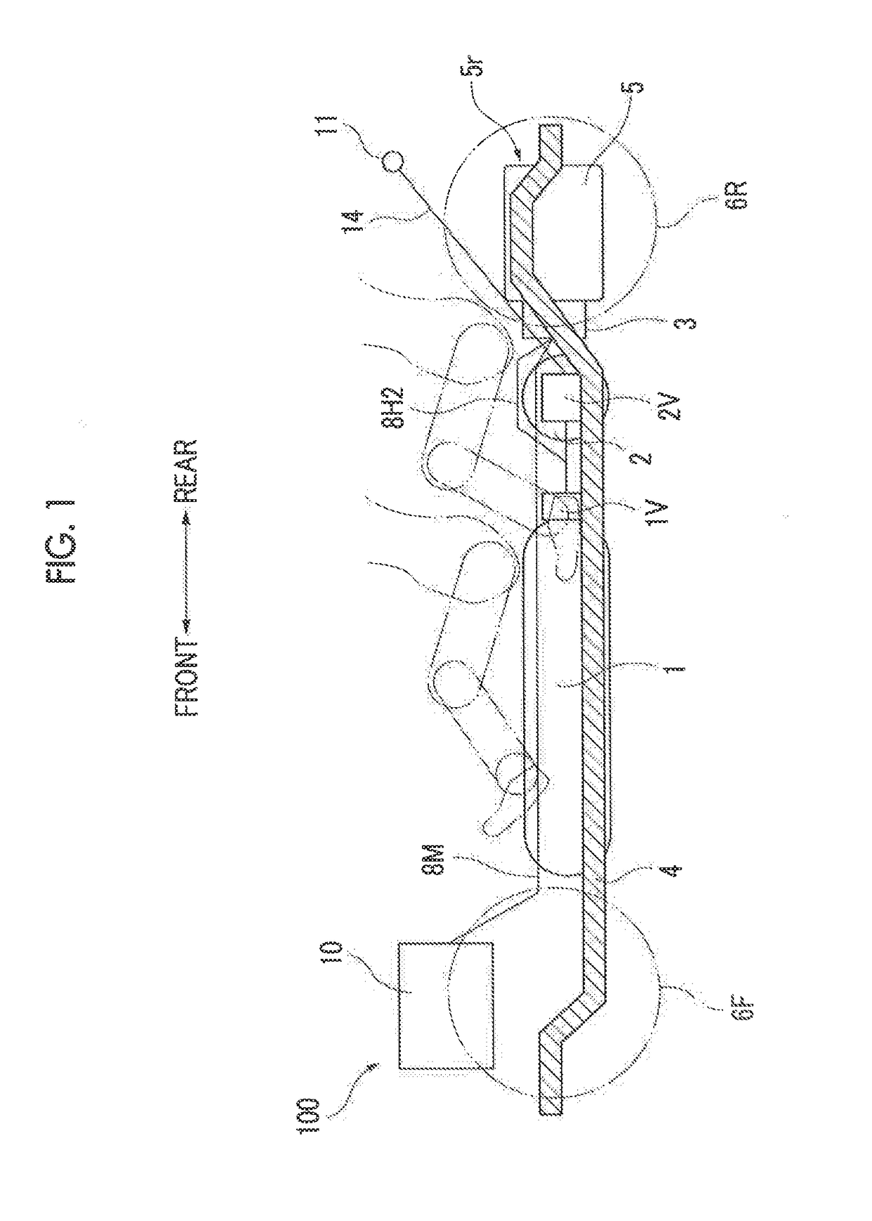
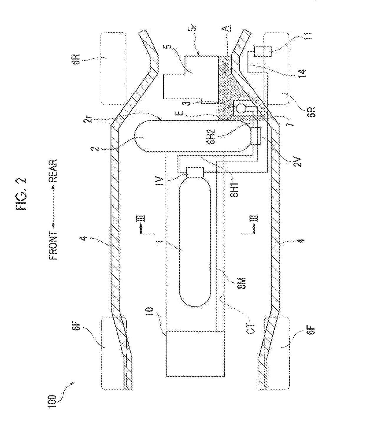
[0032]A fuel cell vehicle 100 according to the present embodiment is a rear-wheel drive vehicle. The fuel cell vehicle 100 includes a front tank 1, a rear tank 2, a pressure-reducing valve 3, side members 4, a motor 5, wheels (front wheels 6F and rear wheels 6R), a fuel cell 10, and so forth.

[0033]The front tank 1 and the rear tank 2 are containers to be filled with hydrogen gas used as fuel. In the fuel cell vehicle 100 according to the present embodiment, the front tank 1 is disposed longitudinally at a position in a center tunnel CT under a floor panel FP such that the longitudinal direction of the front tank 1 coincides with the vehicle front-rear direction (the forward-backward traveling direction) (refer to FIG. 2 and FIG. 3). The rear tank 2 is transversely disposed at a position rearward of th...


PUM


Abstract

A fuel cell vehicle includes a first tank, a second tank, first and second valves for releasing gas, a gas passage for supplying gas to a fuel cell via the first and second valves, a pressure-reducing valve for decompressing the gas, side members disposed on the respective sides of the vehicle, and a motor disposed rearward of the second tank and configured to drive wheels. The first tank is not disposed downstream of the second tank, on the gas passage. The pressure-reducing valve is disposed in a region located rearward of a rear end of the second tank in a vehicle front-rear direction, forward of a rear end of the motor in the vehicle front-rear direction, and between one of the side members and an extended line extended in the vehicle front-rear direction from a side wall of the motor. The pressure-reducing valve is disposed on the second valve side.

Description

INCORPORATION BY REFERENCE[0001]The disclosure of Japanese Patent Application No. 2016-031289 filed on Feb. 22, 2016 including the specification, drawings and abstract is incorporated herein by reference in its entirety.BACKGROUND[0002]1. Technical Field[0003]The disclosure relates to a fuel cell vehicle.[0004]2. Description of Related Art[0005]For example, German Patent Application Publication No. 102009039079 (DE 102009039079 A1) describes a fuel cell vehicle including a first tank, a second tank, and a motor. The first tank storing hydrogen fuel is disposed such that the longitudinal direction of the first tank coincides with the vehicle front-rear direction. The second tank is disposed rearward of the first tank such that the longitudinal direction of the second tank coincides with the vehicle transverse direction (i.e., vehicle right-left direction). In addition, a motor is disposed rearward of the second tank.[0006]In addition, a fuel cell vehicle is provided with a pressure-r...

Claims


Application Information

Patent Timeline
Patent Type & Authority Applications(United States)
IPC IPC(8): B60K15/03B60K15/063B60L11/18
CPCB60K15/03006B60L11/1881B60K15/063B60K2015/03144B60K2015/03315B60K2015/0634B60K2015/0633B60K2015/03328B60K2015/03296B60K1/00B60K15/07B60K2001/001B60K2015/03026B60K2015/0635B60L50/71Y02T90/40
Inventor OKAWACHI, EIJI
Owner TOYOTA JIDOSHA KK
Learn More