
Bearing assembly, arrangement of beams for changing direction of a carriage with the bearing assembly and rail-changing system with said bearing assembly and arrangement of beams

a technology of bearing assembly and beam, which is applied in the direction of bearings, railway tracks, linear bearings, etc., can solve the problems of increasing the risk of locking or an abrupt jump that disturbs the load balance, the relative tolerance between the beams does not have to be relatively small, and the tolerance is reduced. , to achieve the effect of facilitating the rotation of the cam

Active Publication Date: 2017-08-24
CARRILLO LOSTAO LUIS
View PDF2 Cites 0 Cited by
  • Summary
  • Abstract
  • Description
  • Claims
  • Application Information

AI Technical Summary

Benefits of technology

The invention is a bearing assembly that allows for smooth transition between different beams without the risk of locking, regardless of the thickness of the extensions. This is achieved by using a cam with a unique arrangement that reduces friction and allows for a smooth transition without jolts. The bearing assembly can also accommodate different beam types and have relatively large tolerances between the parts. The side segments can also include an inclined portion to facilitate smooth and precise transition.

Problems solved by technology

These types of rails represent a technically complex and costly solution.
This system has several disadvantages, the most important one being the transition of loads during the change in direction.
Furthermore, the defined configuration would not be able to pull the assembly since there would not be any space to transmit momentum towards the wheels.
Furthermore, the system is configured to be used on beams with standard profiles, with wheels adapted to the tilt of the wedge flanges of said profile, which increases the risk of locking or an abrupt jump that disturbs the balance of the load.
The gap between beam segments cannot be very large given the risk of locking.
In case of wanting to pull the rolling assembly, the increase in the thickness of the plates 27 would make the gap between the segments that must be jumped by the main wheels relatively large, leading to the locking or an abrupt jump, disrupting the balance of the load.
Furthermore, the rail-changing mechanism “pushes” the assembly, disrupting the balance of the carried load.

Method used


Image

  • Bearing assembly, arrangement of beams for changing direction of a carriage with the bearing assembly and rail-changing system with said bearing assembly and arrangement of beams
  • Bearing assembly, arrangement of beams for changing direction of a carriage with the bearing assembly and rail-changing system with said bearing assembly and arrangement of beams
  • Bearing assembly, arrangement of beams for changing direction of a carriage with the bearing assembly and rail-changing system with said bearing assembly and arrangement of beams

Examples


Embodiment Construction

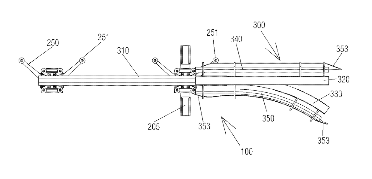
[0038]As is shown in the attached figures, a rail-changing system is illustrated, designated in a general way by the numerical reference 100 which comprises a bearing assembly designated in a general way by the numerical reference 200 and an arrangement of beams designated in a general way by the numerical reference 300.

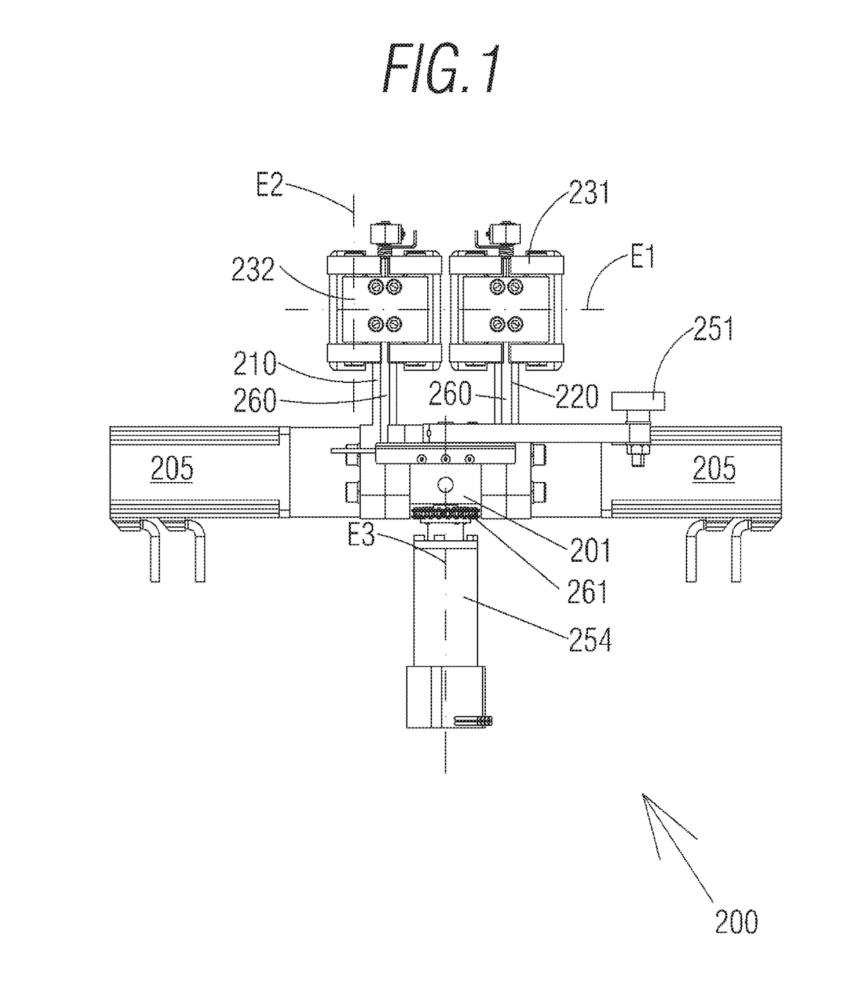
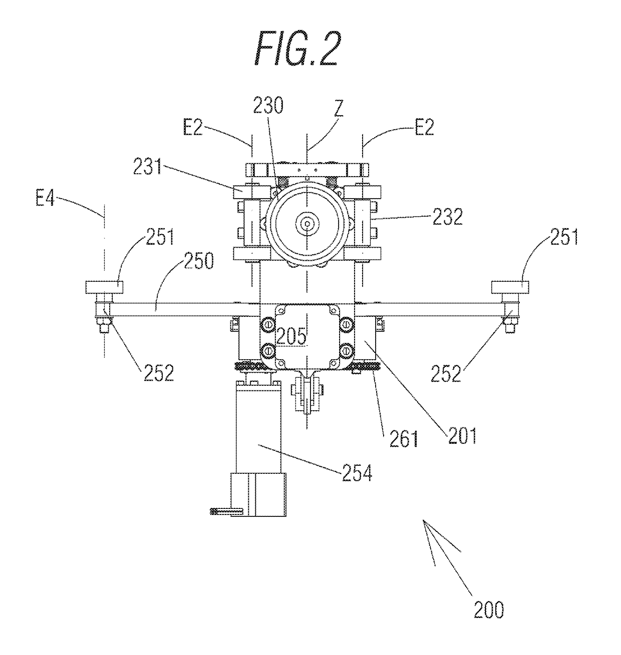
[0039]The bearing assembly 200 is of the type that is linked to a carriage (not shown) of those used in an air transport system on beams. The type of carriage will not be further discussed since it can be any of those available in the market. In the attached figures, two fundamental embodiments of bearing assemblies 200 have been shown, one of a motor type in FIGS. 1-3 and another free, in other words, without motor functions, such as those in FIGS. 4-6.

[0040]Each bearing assembly 200 preferably comprises a frame 201 linked to a pair of elongated extensions 210, 220, such that it defines a configuration similar to a yoke (see FIGS. 1 and 4). The extensions 210, 220 a...


PUM


Abstract

A rail-changing system for air transport systems that comprises a bearing assembly and an arrangement of beams for changing direction, in which the bearing assembly is of the type that is linked to a carriage of an air transport system on beams, and comprises a frame linked to a pair of extensions defining a configuration similar to a yoke, each extension comprising a pair of main wheels with a common rotational axis arranged horizontally, and the main wheels being able to circulate on a beam; the bearing assembly also comprises at least one cam arranged on a rotating basis between the extensions, such that the rotational axis of the cam is arranged vertically, the arrangement of the beams for changing direction of a carriage with a bearing assembly and the beams being rails of the passive type.

Description

RELATED APPLICATION[0001]This application claims the benefit of priority of Spanish Patent Application No. P201630199 filed on Feb. 22, 2016, the contents of which are incorporated herein by reference in their entirety.FIELD AND BACKGROUND OF THE INVENTION[0002]The aim of the present application is to register a bearing assembly, an arrangement of beams and a rail-changing system that incorporate notable inventions.[0003]More specifically, the invention proposes the development of a new rail-changing system that allows for a simple and reliable structure, applicable to a large number of rails, and which does not require high accuracy in the tolerances so that is used correctly.[0004]In the state of the art there are known devices that divert carriages of air transport systems. Some of the known types consist of actuating parts of a track, such that there is a segment that actively diverts the path of the rail. These types of rails represent a technically complex and costly solution....

Claims


Application Information

Patent Timeline
Patent Type & Authority Applications(United States)
IPC IPC(8): E01B7/00B61B3/00
CPCB61B3/00E01B7/00B61B13/04E01B25/26F16C29/005F16C29/04F16C2326/10B61B3/02
Inventor CARRILLO LOSTAO, LUIS
Owner CARRILLO LOSTAO LUIS
Learn More