Heat exchanger and air-conditioning apparatus

a technology of heat exchanger and air conditioner, which is applied in the direction of indirect heat exchanger, light and heating apparatus, refrigeration components, etc., can solve the problems of reducing the operation efficiency of the refrigeration cycle apparatus and increasing the pressure loss of refrigerant, so as to reduce the discharge temperature, enhance the operation efficiency, and reduce the performance of the heat exchanger

Active Publication Date: 2017-08-24
MITSUBISHI ELECTRIC CORP
View PDF1 Cites 14 Cited by
  • Summary
  • Abstract
  • Description
  • Claims
  • Application Information

AI Technical Summary

Benefits of technology

[0008]In the heat exchanger according to the one embodiment of the present invention, each of the relay passages has one inlet connected to the corresponding one of the second heat transfer pipes, and a plurality of outlets each connected to a corresponding one of the plurality of first heat transfer pipes, and distributes, when the heat exchanger acts as an evaporator, the refrigerant flowing from the one inlet, without merging the streams of the refrigerant together, and causes the refrigerant to flow out of the plurality of outlets, with the result that the pressure loss of the refrigerant passing through the relay unit is reduced. Consequently, in a refrigeration cycle apparatus, such as an air-conditioning apparatus, including the heat exchanger as described above, when the refrigerant is changed to the refrigerant having the property of causing the disproportionation, such as R1123 refrigerant and the mixed refrigerant containing R1123 refrigerant, the operation efficiency is enhanced to reduce a discharge temperature so that the refrigerant is prevented from causing the disproportionation. Further, the number of relay passages is smaller than the number of paths in the main heat exchange unit and the sub-heat exchange unit, and hence the occlusion that occurs in the relay passages significantly contributes to a reduction in performance of the heat exchanger. Consequently, the production of the sludge, that is, the occlusion is suppressed in the relay passages to effectively suppress the reduction in performance of the heat exchanger.

Problems solved by technology

As a result, a flow rate of the refrigerant flowing through a refrigerant circuit is increased to lead to an increase in pressure loss of the refrigerant and a reduction in operation efficiency of the refrigeration cycle apparatus.

Method used


Image

  • Heat exchanger and air-conditioning apparatus
  • Heat exchanger and air-conditioning apparatus
  • Heat exchanger and air-conditioning apparatus

Examples


embodiment 1

[0027]A heat exchanger according to Embodiment 1 of the present invention is described.

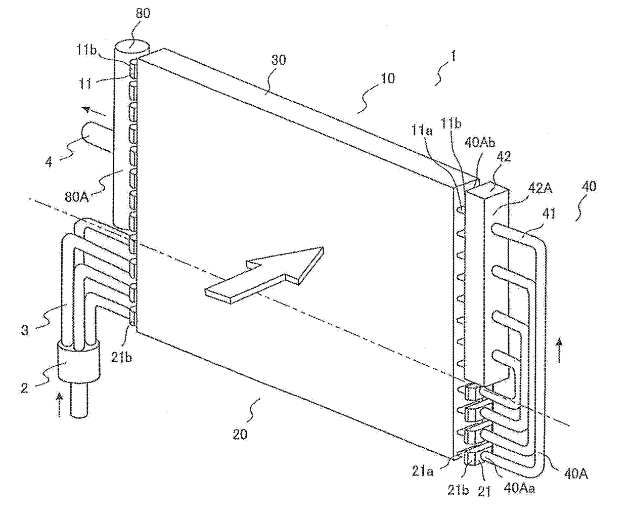
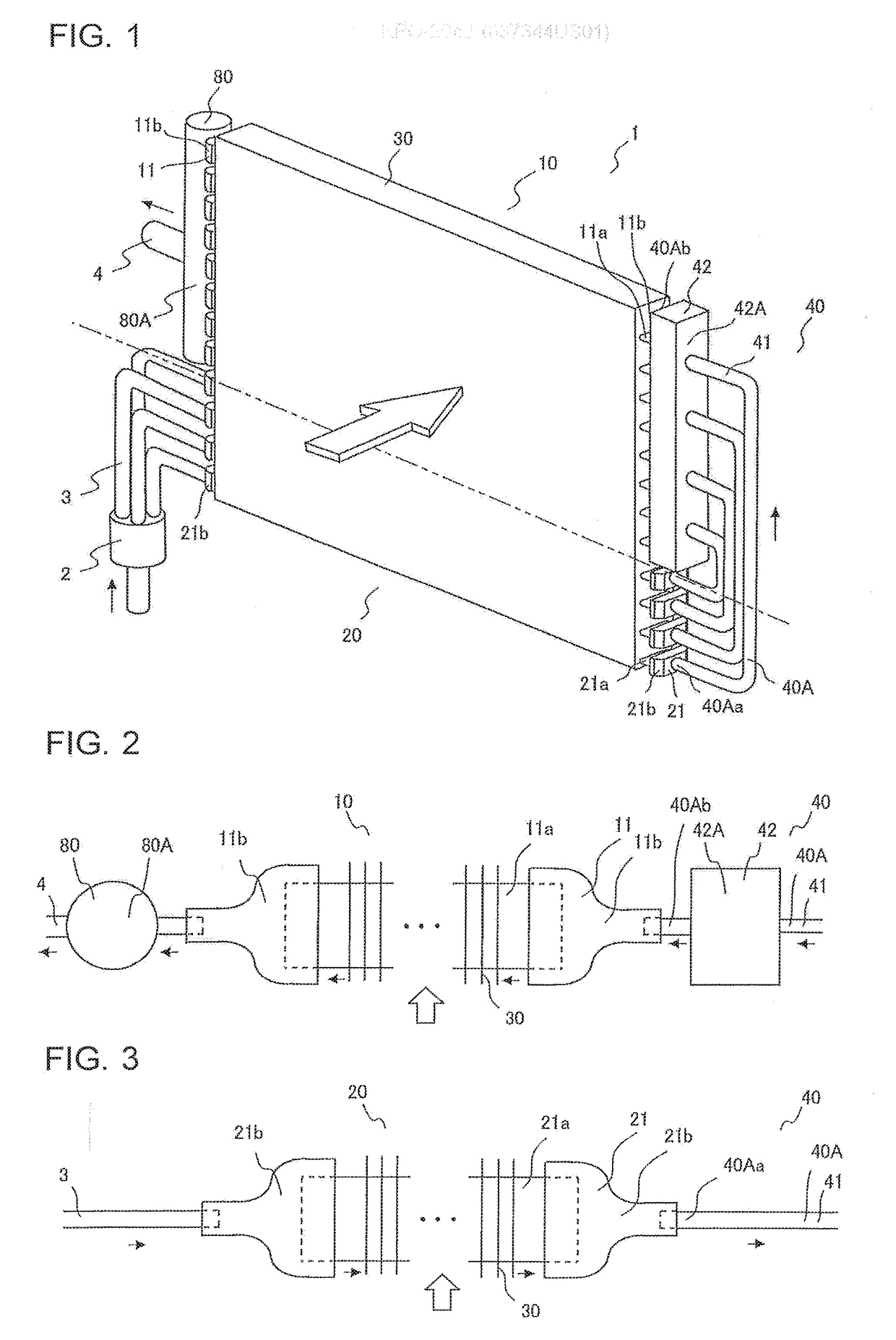
[0028]FIG. 1 is a perspective view of the heat exchanger according to Embodiment 1. FIG. 2 is a top view of a main heat exchange unit and a part of a relay unit of the heat exchanger according to Embodiment 1. FIG. 3 is a top view of a sub-heat exchange unit and a part of the relay unit of the heat exchanger according to Embodiment 1. In FIG. 1 to FIG. 3, a flow of refrigerant when a heat exchanger 1 acts as an evaporator is indicated by the black arrows. Further, in FIG. 1 to FIG. 3, a flow of air for exchanging heat with the refrigerant in the heat exchanger 1 is indicated by the white arrow.

[0029]As illustrated in FIG. 1 to FIG. 3, the heat exchanger 1 includes a main heat exchange unit 10 and a sub-heat exchange unit 20. The sub-heat exchange unit 20 is located below the main heat exchange unit 10 in the gravity direction. The main heat exchange unit 10 includes a plurality of first heat trans...

embodiment 2

[0059]A heat exchanger according to Embodiment 2 of the present invention is described.

[0060]Overlapping description or similar description to that of Embodiment 1 is appropriately simplified or omitted.

[0061]FIG. 9 is a perspective view of the heat exchanger according to Embodiment 2. In FIG. 9, a flow of refrigerant when a heat exchanger 1 acts as an evaporator is indicated by the black arrows. Further, in FIG. 9, a flow of air for exchanging heat with the refrigerant in the heat exchanger 1 is indicated by the white arrow.

[0062]As illustrated in FIG. 9, the relay unit 40 includes a plurality of pipes 41, and a plurality of distributors 43. Each of the plurality of distributors 43 has an inlet connected to a corresponding one of the pipes 41, and a plurality of outlets connected to corresponding ones of the plurality of pipes 41, to thereby form each of a plurality of relay passages 40A. In other words, the relay passages 40A are formed of the pipes 41 and the distributors 43, wit...

embodiment 3

[0065]A heat exchanger according to Embodiment 3 of the present invention is described.

[0066]Overlapping description or similar description to that of each of Embodiment 1 and Embodiment 2 is appropriately simplified or omitted,

[0067]FIG. 10 is a perspective view of the heat exchanger according to Embodiment 3. In FIG. 10, a flow of refrigerant when a heat exchanger 1 acts as an evaporator is indicated by the black arrows. Further, in FIG. 10, a flow of air for exchanging heat with the refrigerant in the heat exchanger 1 is indicated by the white arrow.

[0068]As illustrated in FIG. 10, a relay unit 40 includes a plurality of pipes 41, a plurality of distributors 43, and a stacking type header 42 including a plurality of branch passages 42A formed in the stacking type header 42. Each of the plurality of distributors 43 has an inlet connected to one pipe 41, and a plurality of outlets connected to corresponding ones of the plurality of pipes 41, and one end of each of the plurality of ...


PUM


Abstract

A heat exchanger, in which refrigerant causing disproportionation is used, includes a main heat exchange unit including a plurality of first heat transfer pipes arranged side by side, a sub-heat exchange unit including a plurality of second heat transfer pipes arranged side by side, and a relay unit including a plurality of relay passages connecting the plurality of first heat transfer pipes and the plurality of second heat transfer pipes. Each of the plurality of relay passages has one inlet connected to a corresponding one of the plurality of second heat transfer pipes, and a plurality of outlets each connected to a corresponding one of the plurality of first heat transfer pipes. Each of the plurality of relay passages distributes the refrigerant flowing from the one inlet, without merging streams of the refrigerant together, and causes the refrigerant to flow out of the plurality of outlets.

Description

TECHNICAL FIELD[0001]The present invention relates to a heat exchanger including a main heat exchange unit and a sub-heat exchange unit, and to an air-conditioning apparatus including the heat exchanger.BACKGROUND ART[0002]In a refrigeration cycle apparatus, such as an air-conditioning apparatus, when refrigerant is changed from R410A refrigerant, R4070 refrigerant, and other HFC mixed refrigerants having a lower boiling point than R134a refrigerant to R1234yf refrigerant, a need arises to increase a circulation amount of the refrigerant due to a low operating pressure of R1234yf refrigerant. As a result, a flow rate of the refrigerant flowing through a refrigerant circuit is increased to lead to an increase in pressure loss of the refrigerant and a reduction in operation efficiency of the refrigeration cycle apparatus. To address this problem, the refrigerant has been considered to be changed from R410A refrigerant, R4070 refrigerant, and other HFC mixed refrigerants to refrigerant...

Claims


Application Information

Patent Timeline
Patent Type & Authority Applications(United States)
IPC IPC(8): F25B39/00F25B13/00F28F9/02
CPCF25B39/00F28F9/0275F25B13/00F25B39/028F28F9/0243F25B2500/08F28F9/0278F25B1/00F28F9/02F28F9/026F28D1/0426
Inventor ITO, DAISUKENAKAMURA, SHINHIGASHIIUE, SHINYAMATSUI, SHIGEYOSHIISHIBASHI, AKIRAUGAJIN, YUKINISHIYAMA, TAKUMI
Owner MITSUBISHI ELECTRIC CORP
Why Eureka
Try Eureka