Actively controlled optical tracker with a robot

a robot and optical tracker technology, applied in the field of optical tracking, can solve the problems of not being suitable for operation in the operating room, the disruption of the los between the optical signal and the optical receiver, and the need to maintain a line of sight (los), so as to achieve the effect of minimizing the disruption of the los

Active Publication Date: 2017-08-31
THINK SURGICAL
View PDF14 Cites 31 Cited by
  • Summary
  • Abstract
  • Description
  • Claims
  • Application Information

AI Technical Summary

Benefits of technology

[0017]A process to maintain a line of sight (LOS) between a fiducial marker array and one or more optical receivers is provided that includes: positioning one or more optical receivers in an initial location that minimizes LOS disruption within a system; articulating the fiducial marker array with the one or more movable joints to an initial orientation that optimizes the fiducial marker array within a field of view...

Problems solved by technology

However, a common problem or limitation of such optical tracking systems is the need to maintain a line of sight (LOS) between the optical signals and the optical receivers.
For example, when an object that is being the tracked is in motion, different orientations, positions or other objects may cause a disruption in the LOS between the optical signals and the optical receivers.
For example, electro-magnetic tracking systems (EMTS) can be used without the LOS limitation; however EMTS is not suitable in an operating room due to the potential electro-magnetic interference with other equipment and is currently less accurate than optical tracking systems.
Similarly, accelerometers, and gyroscopes, known as inertial measurement units, can track objects however they intrinsically accumulate error in their position and orientation measurements over time.
Furthermore, when tracking objects in a surgical setting, there may be many instances in which the LOS becomes obstructed.
For example, when operating a tracked tool, optical signals rigidly fixed thereto may be visible at one stage of the procedure but may become obstructed during a subsequent stage.
This may be caused by the POSE of the tracked tool during operation.
Additionally, fluids, operators, as well as other...

Method used


Image

  • Actively controlled optical tracker with a robot
  • Actively controlled optical tracker with a robot
  • Actively controlled optical tracker with a robot

Examples


Embodiment Construction

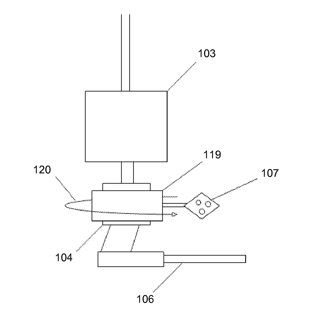
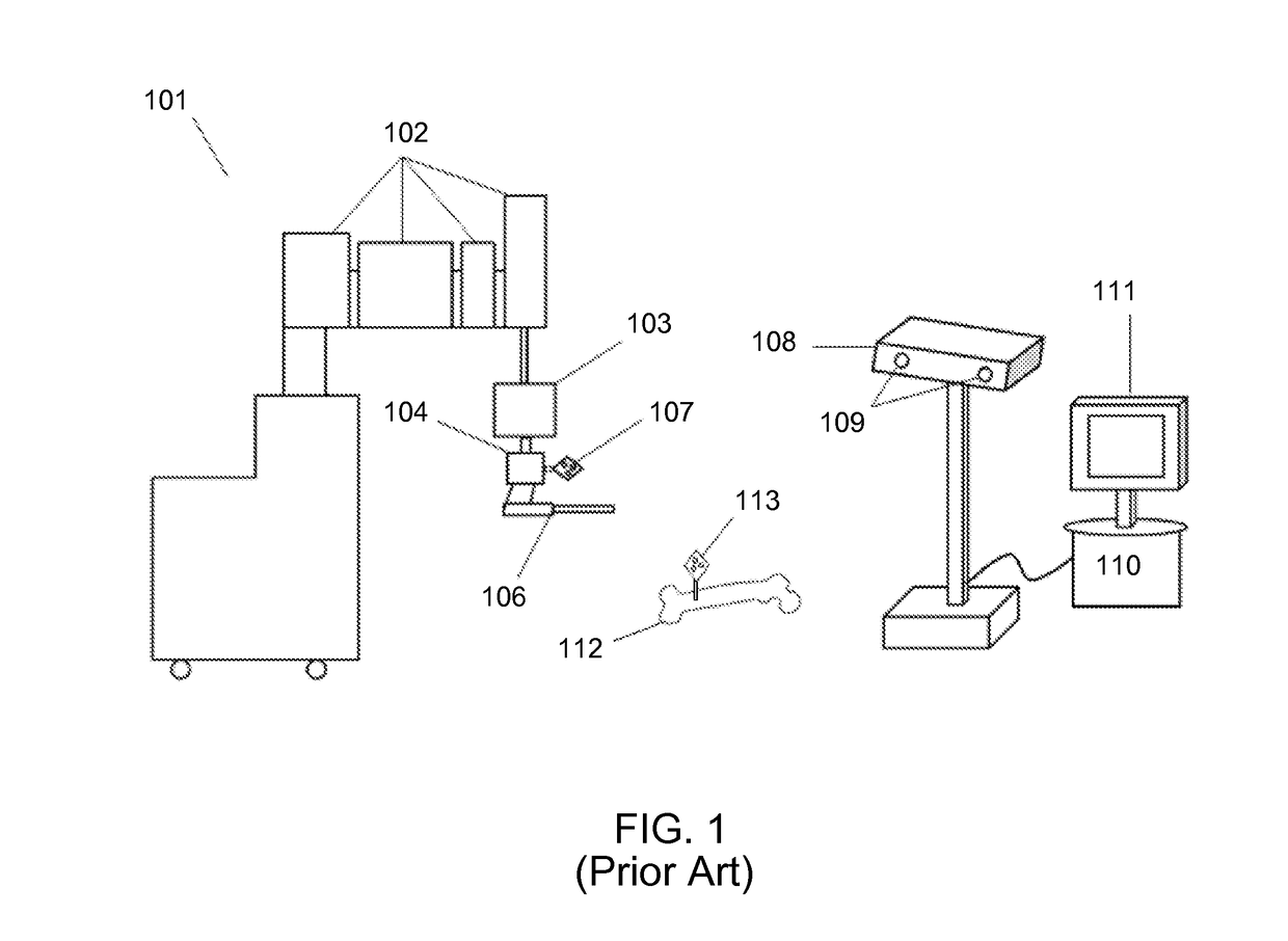
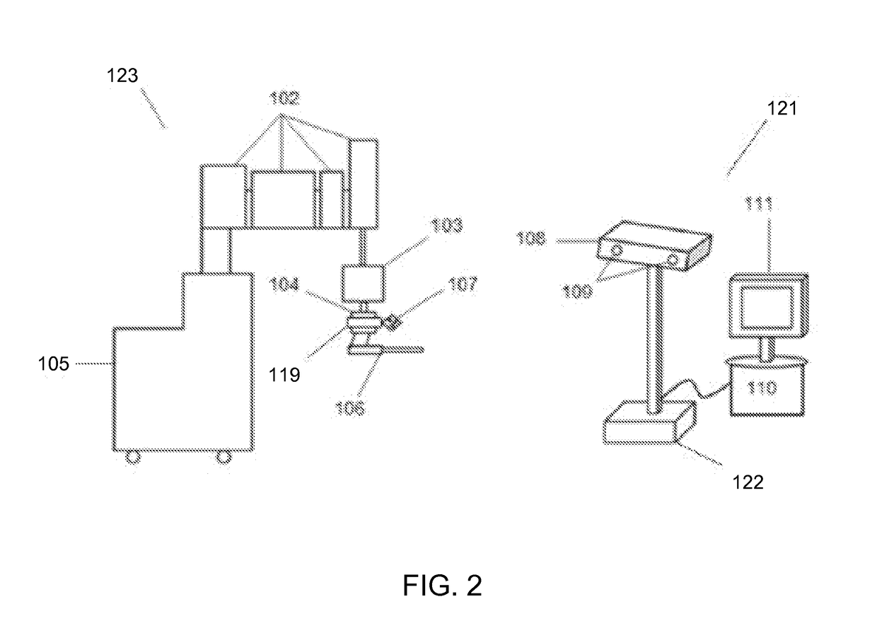
[0038]The invention disclosed herein describes a system and process for the optical tracking of an object, and more particularly to an active controller device incorporated on a computer-assisted device that maintains the line of sight between a tracking array and an optical receiver.

[0039]It is to be understood that in instances where a range of values are provided, the range is intended to encompass not only the end point values of the range but also intermediate values of the range as explicitly being included within the range and varying by the last significant figure of the value. By way of example, a recited range from 1 to 4 is intended to include 1-2, 1-3, 2-4, 3-4, and 1-4.

[0040]As used herein, the term ‘tool’ may be any instrument capable of performing work on an external object. Tools illustratively include a probe, drill bit, laser, cutter, burr, saw blade, shears, forceps, dissectors, cautery hook, cautery spatula, scissors, retractors, graspers; as well as any assembly...


PUM


Abstract

Systems and processes are provided that utilize the accuracy and adaptability of an optical tracking system to track an object by maintaining a line of sight (LOS) between the optical signals from the tracked object and the optical receivers regardless of the position and orientation of the object being tracked. LOS is maintained without having to manually adjust a tracked device or the optical receivers, or be limited to a specified working volume. Instead, whenever the tracked device moves, an active controller device calculates new values for the degrees of freedom of a series of joints holding a tracking array to the tracked object to position and orient the tracking array to maintain visibility to the optical receivers. A computer-assisted or robotic device that decreases operating times, and improves surgical accuracy, without additional user requirements or adjustments to maintain the LOS of the optical tracking system is provided.

Description

CROSS-REFERENCE TO RELATED APPLICATION[0001]This application claims priority of U.S. Provisional Patent Application Ser. No. 62 / 067,001 filed Oct. 22, 2014, and U.S. Provisional Patent Application Ser. No. 62 / 161,693 filed May 14, 2015 which are both incorporated herein by reference.FIELD OF THE INVENTION[0002]The present invention in general relates to the field of optical tracking; and in particular to a new and useful system to maintain a line of sight between a fiducial marker array mounted on a robot and a tracking system.BACKGROUND OF THE INVENTION[0003]The tracking of objects is used in many different industries ranging from military defense to computer assisted surgery. In the medical field, tracking systems have been utilized with medical devices to assist surgeons in performing precision surgery.[0004]Typical configurations and methods for tracking objects are well known in the art. One such method exploits the emission or reflection of signals (light, radiofrequency, infr...

Claims


Application Information

Patent Timeline
IPC IPC(8): A61B34/20A61B34/32A61B90/00A61B34/30
CPCA61B34/20A61B34/30A61B34/32A61B2090/502A61B2034/2048A61B2034/2057A61B2034/2059A61B90/37A61B2034/2055
Inventor TABANDEH, SALEHZUHARS, JOELBONNY, DANIEL PATRICK
Owner THINK SURGICAL
Why Eureka
Try Eureka