Device for fine processing of optically effective surfaces on, in particular, eyeglass lenses

a technology of optically effective surfaces and fine processing, which is applied in the direction of optical surface grinding machines, lens, manufacturing tools, etc., can solve the problems of long processing times, affecting the surface quality of the lens, and reducing the time required for tool change, etc., and achieving the effect of improving the surface quality, and improving the surface quality

Active Publication Date: 2017-08-31
SATISLOH AG
View PDF13 Cites 22 Cited by
  • Summary
  • Abstract
  • Description
  • Claims
  • Application Information

AI Technical Summary

Problems solved by technology

Tool change times thus required can indeed be significantly reduced for industrial production by use of automated tool changers with tool magazines, but this would be involve a substantial outlay on equipment.
By contrast to the above prior art, it is not necessary to accept a compromise which in the case of the prior art polishing machines may ultimately lead to longer processing times than necessary and to worse surface qualities than possible.
In principle, a robot handling system or a hexapod system, which could be displaceably arranged on a rail in front of the polishing cells or at a carriage to hang at the front above the polishing cells, would also be conceivable for workpiece handling, such solution however would be much more expensive.
Such a configuration of the ball head as a universal joint makes it possible, in simple manner, to rotationally drive the polishing plate, which by comparison with an equally conceivable, purely frictionally produced rotational entrainment of the polishing disc by the spectacle lens enables significantly shorter polishing times. Fundamentally, with respect to tiltability and to a rotational drive possibility something similar could, in fact, also be realized by means of a homokinetic joint, but this would involve a significantly greater amount of complication and higher costs.
The movement together of polishing disc and spectacle lens can, in addition, take place in such a manner as a consequence of the resilient (pre-)orientation of the mounting plate that the polishing disc is placed, substantially axially oriented, on the spectacle lens and not, for example, tipped, which could lead to problems particularly in the case of thick or elevated polishing discs.
In principle, it would in fact also be possible to manage such (pre-)orientation of the polishing disc by means of a pneumatically influenced rubber bellows at the mounting plate, but this would be far more complicated.
In fact, other measures would also be conceivable for that purpose such as, for example, retention by permanent or electrically generated magnetic force, but this would be more complicated and possibly problematic with respect to simple attainment of low breakaway moments.

Method used


Image

  • Device for fine processing of optically effective surfaces on, in particular, eyeglass lenses
  • Device for fine processing of optically effective surfaces on, in particular, eyeglass lenses
  • Device for fine processing of optically effective surfaces on, in particular, eyeglass lenses

Examples


Embodiment Construction

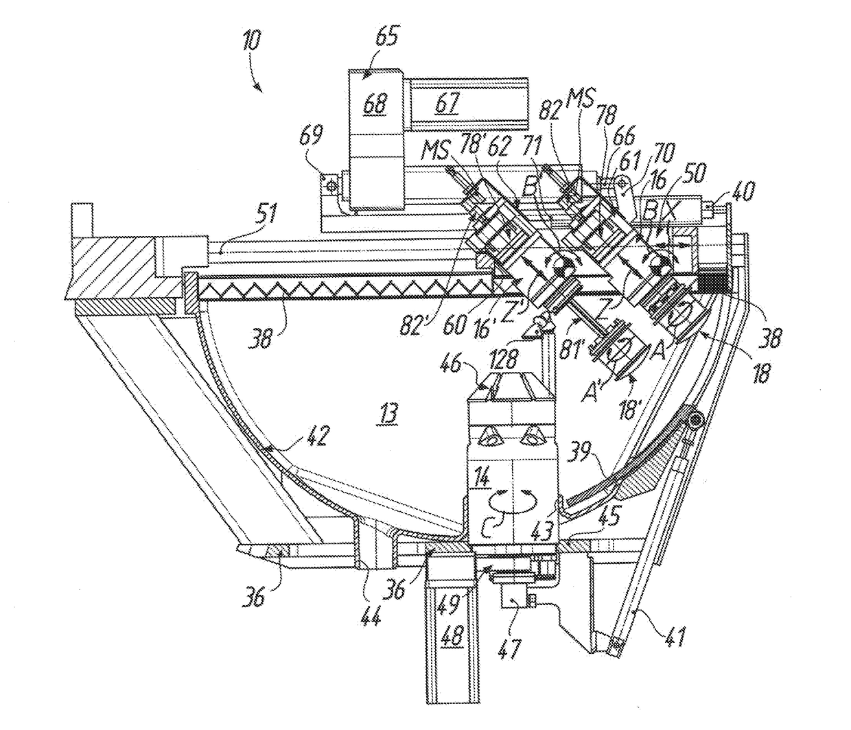
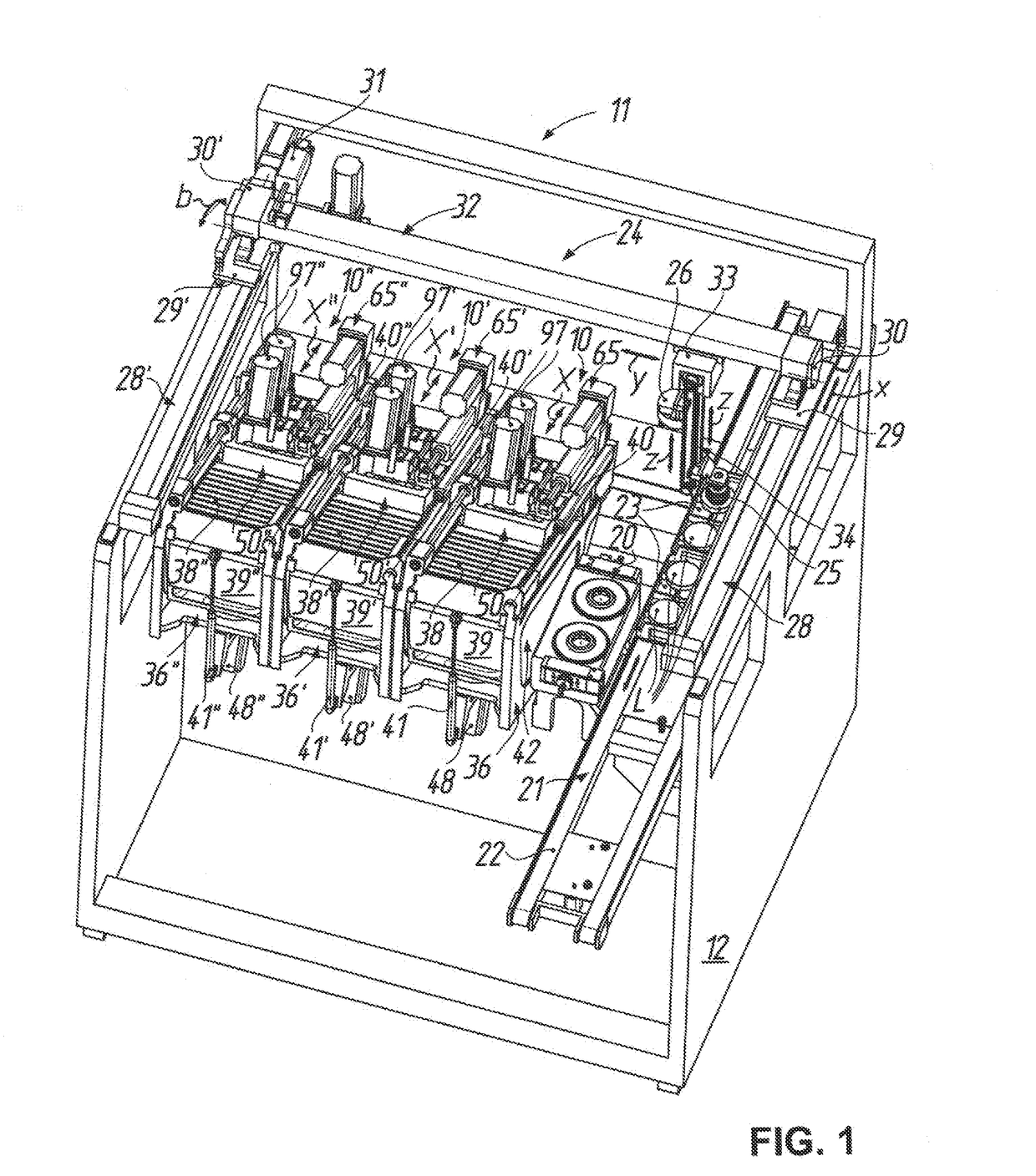
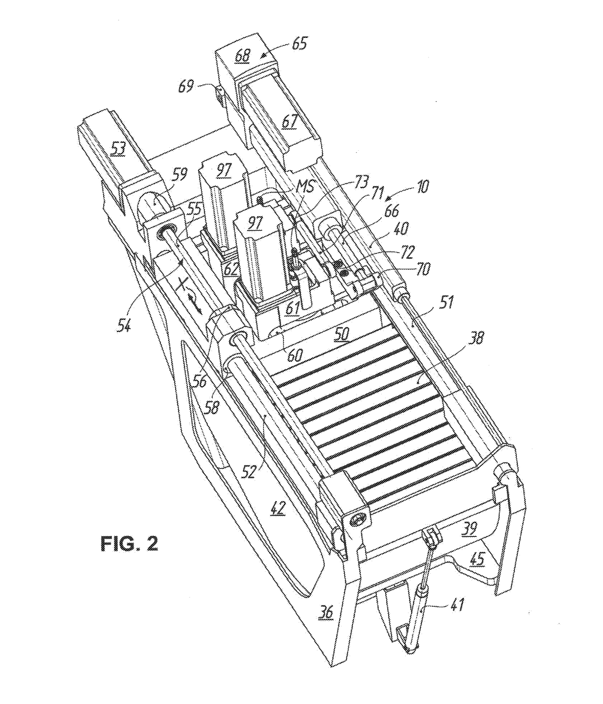
[0051]A polishing machine as preferred case of use or use location of a device 10 for fine processing of optically effective surfaces cc, cx at workpieces such as, for example, spectacle lenses L (cf. FIG. 8) is denoted by 11 in FIG. 1. In the illustrated embodiment, arranged in a common machine frame 12 as polishing cells are—in correspondence with the number of spectacle lens L to be polished—three such devices 10, 10′, 10″ of respectively identical construction. As will be explained in more detail in the following with reference to FIGS. 2 to 7 on the basis of the device 10, which is on the right in FIG. 1, as representative for all three devices 10, 10′, 10″, the device 10 comprises a workpiece spindle 14 which projects into a work space 13 and by way of which a spectacle lens L to be polished, which is usually held by means of a blocking material M on a block piece S for mounting in the workpiece spindle 14 (see, again, FIG. 8), can be driven to rotate about a workpiece axis of...


PUM


Abstract

A device for fine processing of optically effective surfaces on workpieces has a workpiece spindle which protrudes into a working space and by which a workpiece to be polished can be rotationally driven about a workpiece axis of rotation. Two tool spindles are associated with the workpiece spindle and protrude into the working space oppositely to the workpiece spindle. On each tool spindle, a polishing tool can be rotationally driven about a tool axis of rotation and is retained so that the polishing tool can be axially advanced along the tool axis of rotation. Furthermore, the tool spindles can be moved together in relation to the workpiece spindle along a linear axis extending substantially perpendicularly to the workpiece axis of rotation and can be pivoted about different pivoting adjustment axes, which extend substantially perpendicularly to the workpiece axis of rotation and substantially perpendicularly to the linear axis.

Description

TECHNICAL FIELD[0001]The present invention relates in general to a device for fine processing of optically effective surfaces. In particular, the invention relates to a device for fine processing of the optically effective surfaces of spectacle lenses such as used on a large scale in so-called “RX workshops”, i.e. production facilities for manufacture of individual spectacle lenses according to prescription.[0002]If in the following, by way of example, reference is made to “spectacle lenses” for workpieces with optically effective surfaces there is to be understood by that not only spectacle lenses of mineral glass, but also spectacle lenses of all other customary materials such as polycarbonate, CR 39, HI index, etc., thus also plastics material.PRIOR ART[0003]Processing of optically effective surfaces of spectacle lenses by material removal can be roughly divided into two processing phases, namely initially preparatory processing of the optically effective surface for producing th...

Claims


Application Information

Patent Timeline
Patent Type & Authority Applications(United States)
IPC IPC(8): B24B13/00B24B27/00
CPCB24B27/0076B24B13/0037B24B13/00B24B13/005B24B9/14
Inventor WALLENDORF, STEFFENSCHAFER, HOLGERPHILIPPS, PETERKAUFMANN, ANDREAS
Owner SATISLOH AG
Why Eureka
Try Eureka