

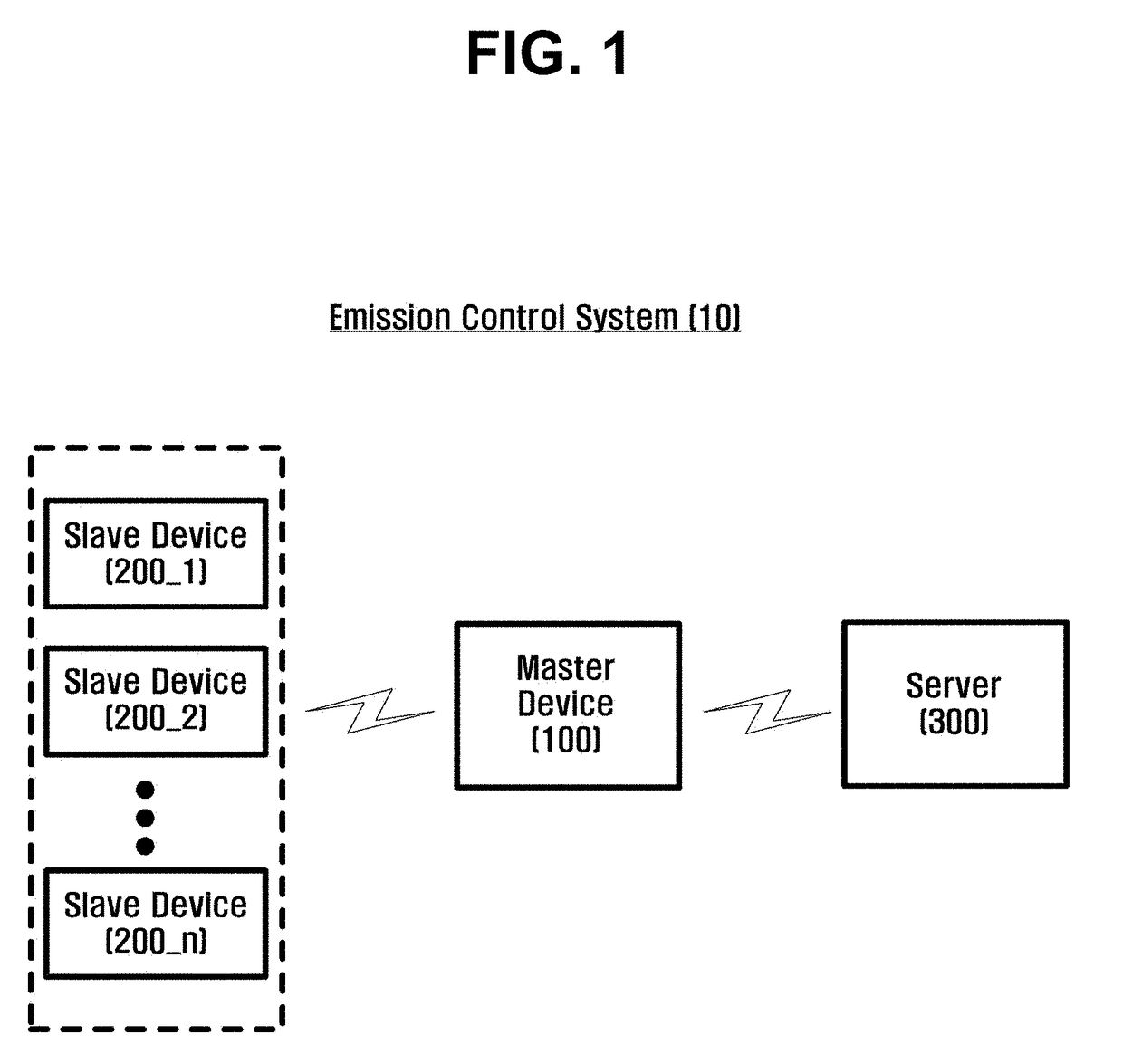
Emission control system using barcode information
a technology of emission control system and barcode information, applied in the field of emission control system, can solve the problems of difficult to achieve a cheering effect, difficult to form systematic lighting patterns or shapes, and difficult to accurately calculate the position of lighting devices, so as to prevent defects, improve the cheering effect caused by various emission patterns, and improve quality
- Summary
- Abstract
- Description
- Claims
- Application Information
AI Technical Summary
Benefits of technology
Problems solved by technology
Method used
Image

Examples
Embodiment Construction
[0058]The inventive concept and methods of accomplishing the same may be understood more readily by reference to the following detailed description of embodiments and the accompanying drawings. However, the inventive concept may be embodied in many different forms, and should not be construed as being limited to the embodiments set forth herein. Rather, these embodiments are provided so that this disclosure will be thorough and complete and will fully convey the concept of the invention to those skilled in the art, and the inventive concept will only be defined by the appended claims. Like numbers refer to like elements throughout.
[0059]Unless otherwise defined, all terms (including technical and scientific terms) used herein have the same meaning as commonly understood by one of ordinary skill in the art to which this invention belongs. It will be further understood that terms, such as those defined in commonly used dictionaries, should be interpreted as having a meaning that is co...
PUM
 Abstract
Description
Claims
Application Information