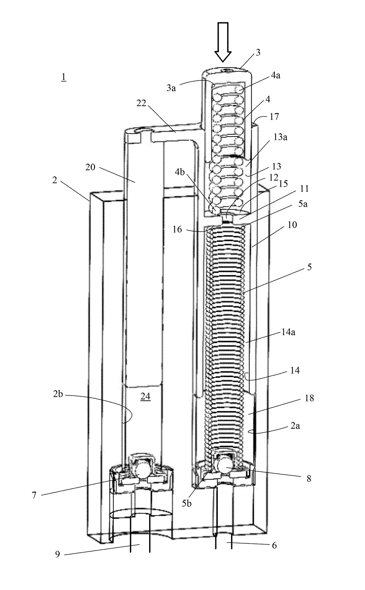
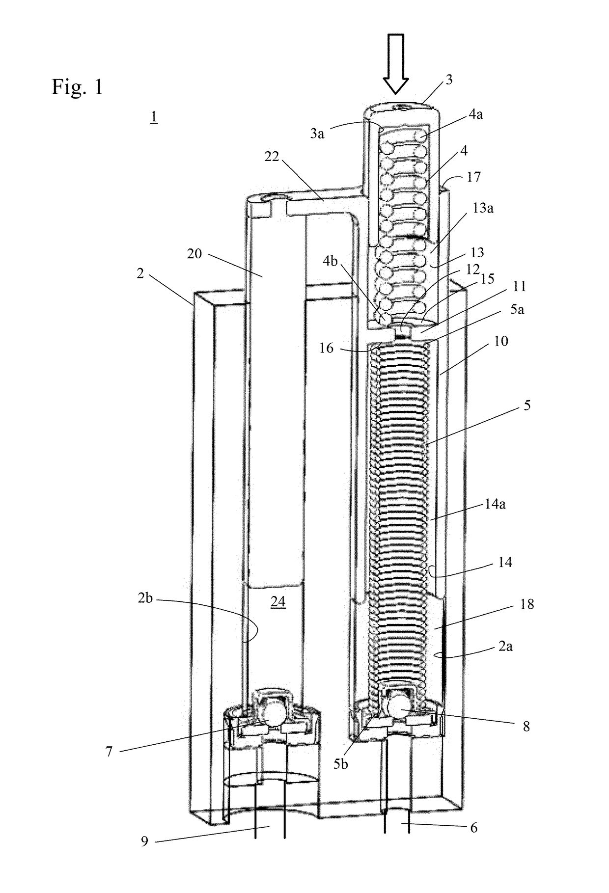
Tensioner with spring force control in a second bore
a technology of spring force control and tensioner, which is applied in the direction of machine/engine, belt/chain/gearing, machine/engine, etc., can solve the problem that the spring force of the chain drive tensioner is often too high for most operating conditions, and achieve the effect of improving drive efficiency
- Summary
- Abstract
- Description
- Claims
- Application Information
AI Technical Summary
Benefits of technology
Problems solved by technology
Method used
Image
Examples
second embodiment
[0038]FIGS. 2a-2b shows a tensioner of a second embodiment using passive control to tension a chain under various conditions; FIG. 2a is tensioning a chain without high loads; and FIG. 2b is tensioning a chain with high load.
[0039]The tensioner includes a housing 102 having a first axially extending bore 102a parallel to a second axially extending bore 102b. While the second bore 102c of the housing 102 is shown as being parallel to the first bore 102a, the second bore 102c may be perpendicular to the first bore 102a or at some other angle relative to the first bore 102a.
[0040]Slidably received within the first axially extending bore 102a is a first piston 103. The first piston 103 has a body with a first end 103a, a second end 103c, and a hollow interior 103b. Present within the hollow interior 103b of the first piston 103 is a first piston spring 104. The first piston spring 104 has a first end 104a in contact with the interior 103b of the first piston 103 or a volume reducer 105...
third embodiment
[0055]FIGS. 3a-3b shows a tensioner of a third embodiment using passive control to tension a chain under various conditions; FIG. 3a is tensioning a chain without high loads; and FIG. 3b is tensioning a chain with high load.
[0056]The tensioner includes a housing 102 having a first axially extending bore 102a parallel to a second axially extending bore 102c. While the second bore 102c of the housing 102 is shown as being parallel to the first bore 102a, the second bore 102c may be perpendicular to the first bore 102a or at some other angle relative to the first bore 102a.
[0057]Slidably received within the first axially extending bore 102a is a first piston 103. The first piston 103 has a body with a first end 103a, a second end 103c, and a hollow interior 103b. Present within the hollow interior 103b of the first piston 103 is a first piston spring 104. The first piston spring 104 has a first end 104a in contact with the interior 103b of the first piston 103 or a volume reducer 105 ...
fourth embodiment
[0071]FIGS. 4a-4b shows a tensioner of a fourth embodiment using passive control to tension a chain under various conditions; FIG. 4a is tensioning a chain without high loads; and FIG. 4b is tensioning a chain with high load.
[0072]The tensioner includes a housing 102 having a first axially extending bore 102a parallel to a second axially extending bore 102b. While the second bore 102c of the housing 102 is shown as being parallel to the first bore 102a, the second bore 102c may be perpendicular to the first bore 102a or at some other angle relative to the first bore 102a.
[0073]Slidably received within the first axially extending bore 102a is a first piston 103. The first piston 103 has a body with a first end 103a, a second end 103c, and a hollow interior 103b. Present within the hollow interior 103b of the first piston 103 is a first piston spring 104. The first piston spring 104 has a first end 104a in contact with the interior 103b of the first piston 103 or a volume reducer 105...
PUM
 Abstract
Description
Claims
Application Information
 - R&D
- Intellectual Property
- Life Sciences
- Materials
- Tech Scout
- Unparalleled Data Quality
- Higher Quality Content
- 60% Fewer Hallucinations
Browse by: Latest US Patents, China's latest patents, Technical Efficacy Thesaurus, Application Domain, Technology Topic, Popular Technical Reports.
© 2025 PatSnap. All rights reserved.Legal|Privacy policy|Modern Slavery Act Transparency Statement|Sitemap|About US| Contact US: help@patsnap.com


