Rigid Container for Precision Liquid Measuring and Dispensing

Inactive Publication Date: 2017-09-07
MOHAWK GRP INC
View PDF3 Cites 0 Cited by
  • Summary
  • Abstract
  • Description
  • Claims
  • Application Information

AI Technical Summary

Benefits of technology

The patent describes an oil bottle with calibrated markings on the side and a flexible lid that can increase pressure. The bottle is easy to clean and maintain, and all surfaces are covered with an oliophobic substance to prevent oil buildup. The patent also mentions that the oil bottle can be made from different materials like plastic, glass, metal, ceramic, and composite. The technical effects of this patent are to provide a convenient and easy-to-use oil bottle with precise liquid level indications and the ability to easily pour out liquid by tilting the receptacle or increasing pressure by pressing the flexible lid.

Problems solved by technology

However, Sanguinet, et al. fail to teach precisely measuring the amount of fluid in the bowl before dispensing the fluid onto foodstuffs or a cooking vessel, or siphoning all or a portion of the fluid back into the original bottle.
However, Davenport fails to teach a first reservoir is rigid and instead teaches away that the first reservoir is flexible.
However, Welland fails to teach a rigid container that can dispense a precise amount of liquid.
In U.S. Pat. No. 5,833,124 (entitled “Fluid Dispensing Device”), Groves, et al. teach a “fluid dispensing device which is used to measure [a] desire[d] amount of fluid from a bottle, such as a deformable resilient plastic bottle, and dispense that measured amount.” However, Groves, et al. fail to teach rigid dispensing device.

Method used


Image

  • Rigid Container for Precision Liquid Measuring and Dispensing
  • Rigid Container for Precision Liquid Measuring and Dispensing
  • Rigid Container for Precision Liquid Measuring and Dispensing

Examples


Embodiment Construction

[0036]The following is a non-limiting written description of embodiments illustrating various aspects of this invention.

[0037]As used herein, the term receptacle is deemed to mean any multi-dimension container capable of containing a liquid. The term receptacle is deemed to be synonymous with a chamber, container, box, bottle, vessel, thermos, jar, and / or other type of liquid containment vehicle.

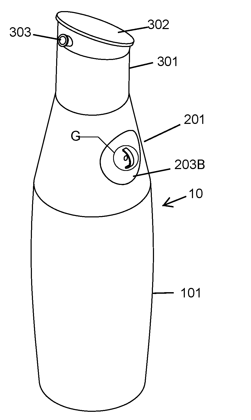
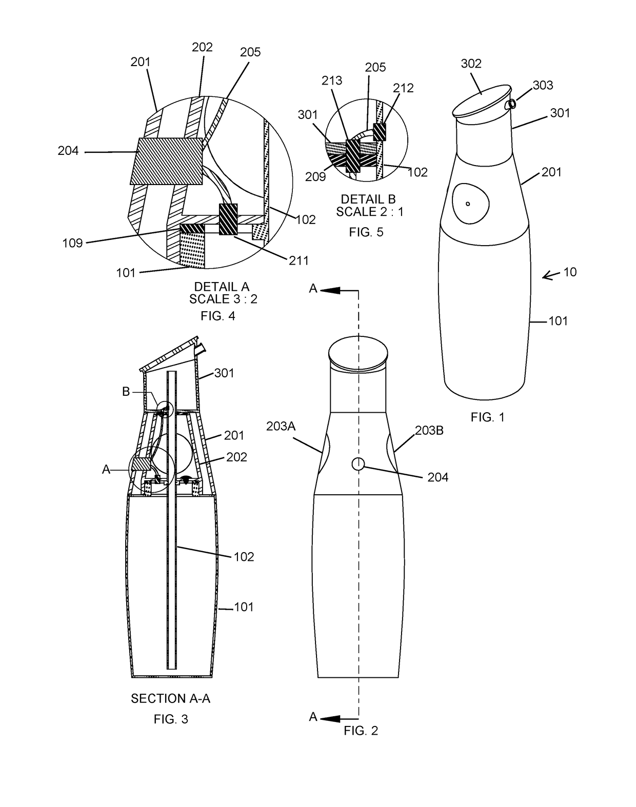
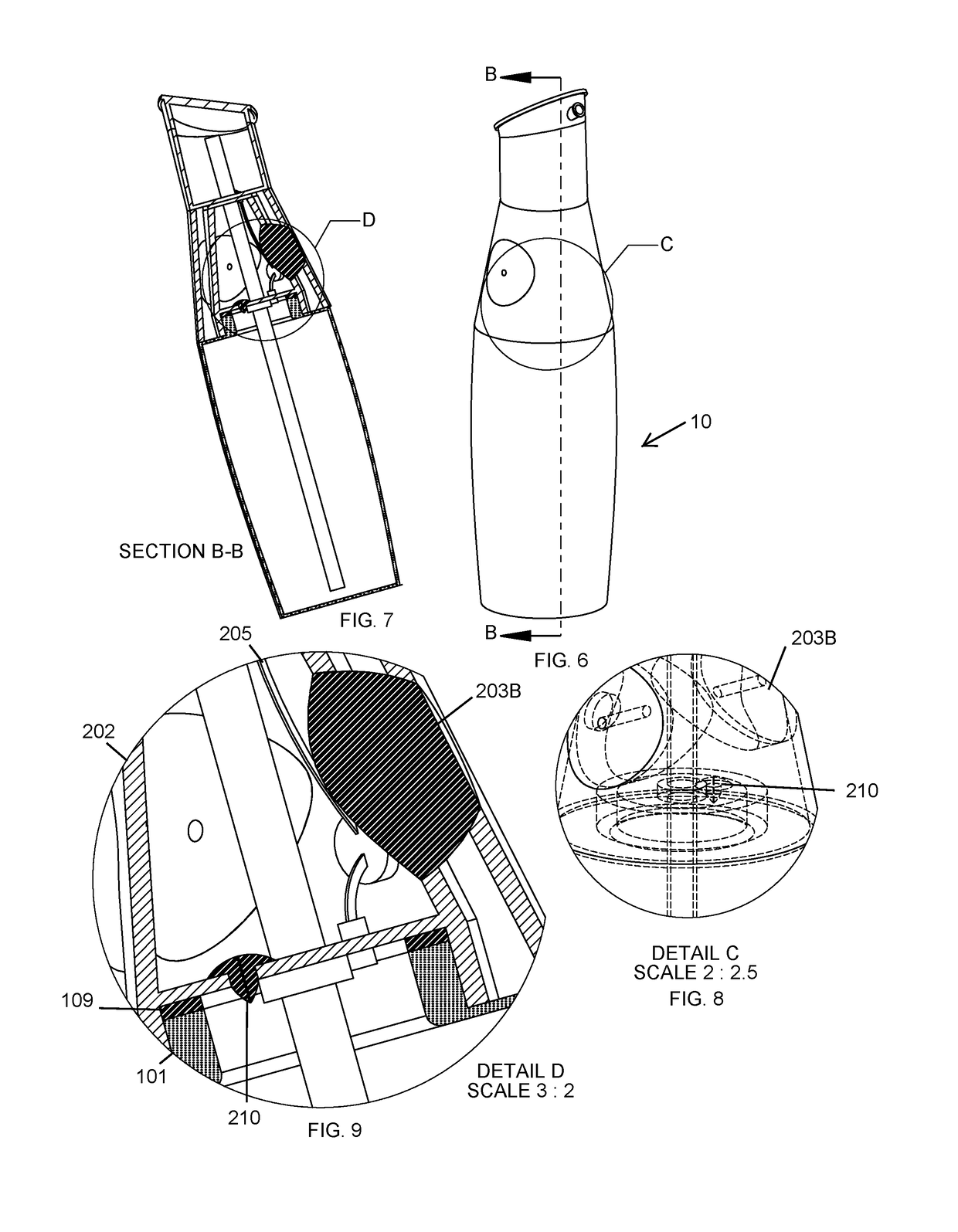
[0038]FIG. 1 shows a perspective view of a receptacle 10 with a first chamber 101, a second chamber 201, and a third chamber 301. In a preferred embodiment the first chamber 101, second chamber 201, and third chamber 301 are all rigid and do not deform when squeezed or otherwise pressed by a human hand. Liquid from the third chamber 301 can exit the receptacle 10 via spout 303. The third chamber 301 has an optionally removable and flexible lid 302 that can be depressed to increase pressure in the third chamber 301 which controllably forces the liquid in the third chamber 301 out of the third...


PUM


Abstract

This invention teaches dispensing a precise amount of liquid from a rigid vessel using a combination of valves, plugs, and diaphragms. In particular, a rigid container with a connected measuring receptacle can dispense oil. A user can depress at least one diaphragm on the rigid container to pressurize a chamber, forcing the liquid upwards into a hollow tube and into the measuring receptacle. The hollow tube, traversing the interior of the container, has at least one orifice at both the proximal and distal ends. The user can calibrate the amount of liquid in the measuring receptacle by activating a release valve or stopper to remove the liquid from the measuring receptacle and back into the container. In addition, a flexible and optionally removable lid covers the measuring receptacle. This lid can be depressed to pressurize the measuring receptacle and expel the liquid from an orifice on the measuring receptacle.

Description

PRIORITY CLAIM[0001]This application claims priority to U.S. Provisional Patent Application Ser. No. 62 / 484,803 filed on Apr. 12, 2017, entitled “Rigid Container for Precision Liquid Measuring and Dispensing,” the disclosure of which is hereby incorporated by reference.FIELD OF INVENTION[0002]The present invention relates to the field of gaskets and valves. In particular, this invention teaches extracting fluid from a first vessel into a measuring receptacle using a combination of valves, plugs, and diaphragms. In addition, this invention teaches enabling the extracted fluid in the measuring receptacle to flow back into the first vessel using a combination of valves, plugs, and diaphragms without wasting or contaminating any of the fluid.BACKGROUND OF THE INVENTION[0003]The kitchen goods industry has a myriad of devices to assist with food preparation and improve food sanitation. In addition, these devices help reduce food waste and make it easier for chefs to use precise amounts of...

Claims


Application Information

Patent Timeline
IPC IPC(8): G01F11/28B65D47/06G01F15/00
CPCG01F11/28B65D47/06G01F15/005
Inventor PAVIS, SARAH
Owner MOHAWK GRP INC
Why Eureka
Try Eureka