Piston for a hydraulic valve for a cam phaser and hydraulic valve for the cam phaser

a technology of hydraulic valve and cam phaser, which is applied in the direction of fluid-pressure actuators, engine components, machines/engines, etc., can solve the problems of high assembly complexity and achieve the effect of improving the reaction time and reaction speed of the cam phaser, avoiding complex development work, and being easy to produ

Inactive Publication Date: 2017-09-14
ECO HLDG 1 GMBH
View PDF1 Cites 16 Cited by
  • Summary
  • Abstract
  • Description
  • Claims
  • Application Information

AI Technical Summary

Benefits of technology

[0020]The hydraulic valve according to the invention is flexible when modifying flow through openings relative to a piston travel so that hydraulic valves which have at least two connection openings per operating connection can be reduced to one connection opening per operating connection. This is caused by the fact that the hydraulic valve according to the invention has check valves that are movable together with the piston and which move relative to the connection openings whereas the check valves are fixated in the prior art hydraulic valves.
[0021]Furthermore the piston can be used in its basic geometry for different variants of the hydraulic valve due to an exterior geometry of the piston being simple to produce so that complex development work can be avoided. Thus, the hydraulic valve can be produced in a cost effective manner.
[0022]In one embodiment of the hydraulic valve according to the invention the supply connection is arranged at a first end of the tubular housing so that the piston can be impacted by the flow directly and without loss inducing flow deflection. This improves reaction time and reaction speed of the cam phaser.
[0023]In another embodiment the hydraulic valve includes additional connection openings for controlling a cam phaser with center position locking. It is an advantage of the hydraulic valve according to the invention over a prior art hydraulic valve that is provided for a cam phaser with center position locking that a required installation space is substantially reduced. This helps to implement a compact cam phaser which has a reduced installation space requirement compared to a prior art cam phaser with center positon locking.

Problems solved by technology

This either requires a complex housing configuration for receiving and securing the check valves or the housing is configured in plural components and requires a high level of assembly complexity.

Method used


Image

  • Piston for a hydraulic valve for a cam phaser and hydraulic valve for the cam phaser
  • Piston for a hydraulic valve for a cam phaser and hydraulic valve for the cam phaser
  • Piston for a hydraulic valve for a cam phaser and hydraulic valve for the cam phaser

Examples


first embodiment

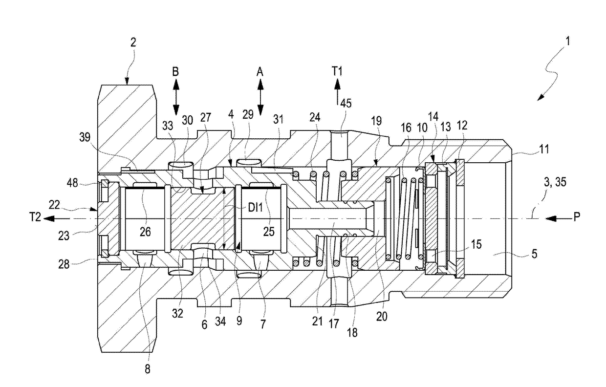
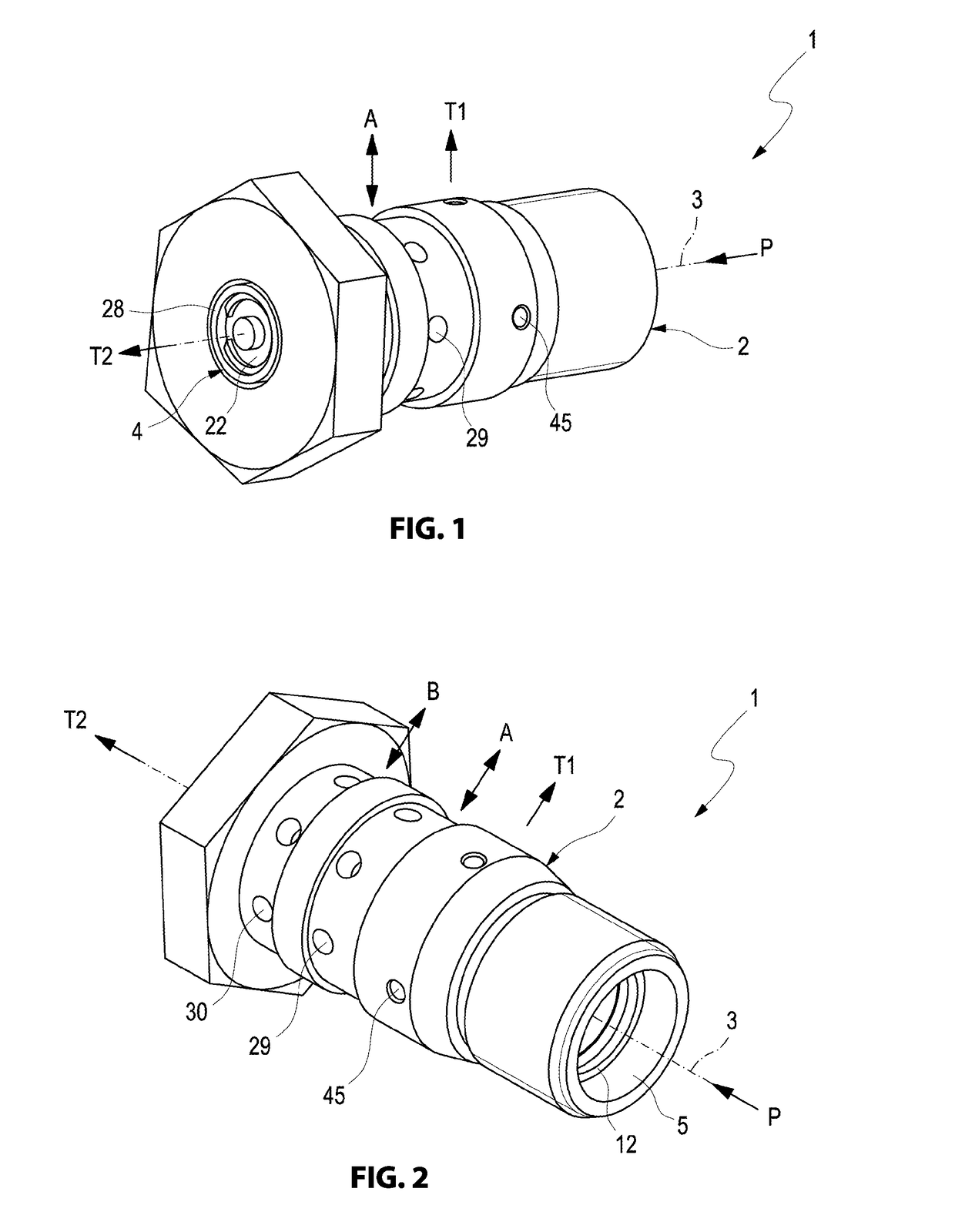
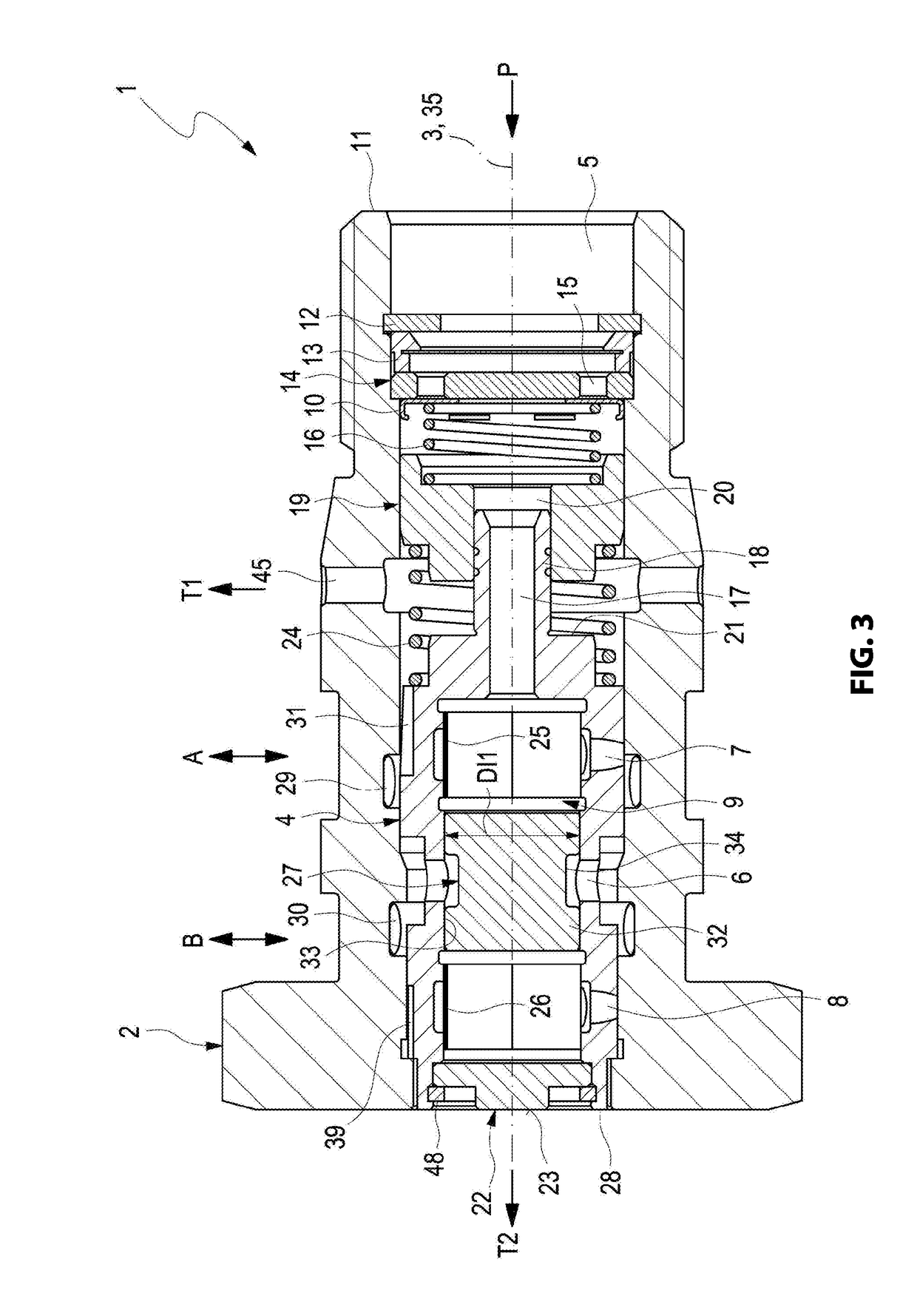
[0046]A hydraulic valve 1 according to the invention for a cam phaser for a cam that is not illustrated in more detail is configured in a first embodiment according to FIG. 1. The hydraulic valve 1 is configured as a central valve to be received in a rotor of a cam phaser that is not illustrated in more detail. Put differently, the hydraulic valve 1 is received in a central opening of the cam phaser, so that it is at least partially enveloped by the receiving cam phaser.

[0047]The hydraulic valve 1 includes a housing 2 which is configured flow able. In order to hydraulically supply the cam phaser plural connections A, B, P, T1, T2 are provided at the housing 2. In the housing 2 a piston 4 is received in a central opening 5 of the housing 2 so that the piston is axially movable along a first longitudinal axis 3 of the hydraulic valve 1. The housing 2 is configured substantially tubular.

[0048]The cam phaser facilitates adjusting opening and closing times of gas exchange valves of the i...

second embodiment

[0070]FIG. 12 illustrates the hydraulic valve 1 according to the invention with the so called center position locking in a symbolic representation in various positions.

[0071]Due to the serial arrangement of the locking connections S, L a greater operating travel of the piston 4 or an extended stroke of the piston 4 is achieved. In order for the connections A, B, T1, T2, S, L to be flowed through in a functionally correct manner for cam phasing it is necessary to associate an additional flow through opening with the second operating connection B, wherein this additional flow through opening is designated as the flow through opening 40 and arranged in the piston 4. Depending on the positioning of the operating connections A, B the additional flow through opening could also be associated with the first operating connection A. This is a function of the configuration of the hydraulic valve 1.

[0072]In order to prevent a flow through of this fourth flow through opening 40 from the inner ca...

third embodiment

[0078]FIGS. 17 and 18 illustrate the hydraulic valve 1 according to the invention in a third embodiment wherein the flow through openings 6, 7, 8 are configured as slotted holes. The piston cover 22 is secured at the piston 4 by an additional safety element 48 configured as a snap ring.


PUM


Abstract

A piston for a hydraulic valve of a rotation phaser, wherein the piston is configured hollow cylindrical, wherein the piston is axially movable in a central opening extending along a first longitudinal axis of a housing of the hydraulic valve, wherein operating connections of the housing are opened and closed according to a position of the piston, wherein the piston includes check valves which prevent an unintentional outflow of a hydraulic fluid flowing through the piston from an inner cavity of the piston in flow through openings of the piston associated with the operating connections, wherein the piston is configured with check valves in its inner cavity that open towards its interior cavity, wherein the check valves are fixated by a spacer element that is arranged between the two check valves. The invention also relates to a hydraulic valve for a rotation phaser of a cam shaft.

Description

RELATED APPLICATIONS[0001]This application claims priority from and incorporates by reference U.S. Provisional Patent Application 62 / 307,745 filed on Mar. 14, 2016.FIELD OF THE INVENTION[0002]The invention relates to a piston for a hydraulic valve of a cam phaser according to the preamble of patent claim 1 and a hydraulic valve for a cam phaser according patent claim 10.BACKGROUND OF THE INVENTION[0003]Hydraulic valves for cam phasers for internal combustion engines are well known in the art. The hydraulic valve includes a piston that is axially movable in a housing of the hydraulic valve and that controls a hydraulic loading of the cam phaser. Hydraulic valves come in many different configurations. The housing is configured hollow cylindrical. The piston is also configured hollow cylindrical. Controlling the cam phaser is done hydraulically by positioning the flowable piston and opening and closing connections configured in the housing accordingly.[0004]The publication documents DE...

Claims


Application Information

Patent Timeline
Patent Type & Authority Applications(United States)
IPC IPC(8): F01L1/344F15B13/042
CPCF01L1/3442F01L2001/34426F15B13/0426
Inventor BROWER, BRENTSTANHOPE, DANIEL
Owner ECO HLDG 1 GMBH
Why Eureka
Try Eureka