
Centrifugal pressure booster and method for modifying or constructing a centrifugal pressure booster

a centrifugal pressure booster and centrifugal pump technology, which is applied in the direction of liquid fuel engines, electrical apparatus, dynamo-electric machines, etc., can solve the problems of restricting the rotation of the rotor, shortening the service life of the pressure booster, and restricting the maximum power rating and rotations per minute, so as to achieve the effect of enhancing the coolant flow

Inactive Publication Date: 2017-09-14
AKER SOLUTIONS AS
View PDF3 Cites 4 Cited by
  • Summary
  • Abstract
  • Description
  • Claims
  • Application Information

AI Technical Summary

Benefits of technology

The invention relates to a pressure booster that uses a rotor stator gap coolant inlet pump to ensure a steady flow of coolant through the gap, which better removes frictional heat and extends the motor's lifetime, increases power rating, and allows for higher rpm operation. The pump is a combined balancing ring and impeller that can be directed into the rotor stator gap by an external cover or similar device. The balancing device minimizes vibrations and misalignments on the shaft. Overall, this design simplifies installation and maintenance of the pressure booster and provides better cooling performance compared to having blades in the rotor stator gap.

Problems solved by technology

However, numerous special challenges related to subsea pressure boosting limit the use.
Two major challenges for subsea pressure boosting are to improve reliability and to increase the maximum power and speed of the subsea pressure booster.
A large friction loss in the gap between the rotor and the stator, especially at high speeds, restricts the rotation of the rotor.
The friction generates heat, restricting the maximum power rating and rotations per minute and shortening the service life of the pressure booster.
However, this will reduce the efficiency of the magnetic coupling and hence also the motor efficiency.

Method used


Image

  • Centrifugal pressure booster and method for modifying or constructing a centrifugal pressure booster
  • Centrifugal pressure booster and method for modifying or constructing a centrifugal pressure booster
  • Centrifugal pressure booster and method for modifying or constructing a centrifugal pressure booster

Examples


Embodiment Construction

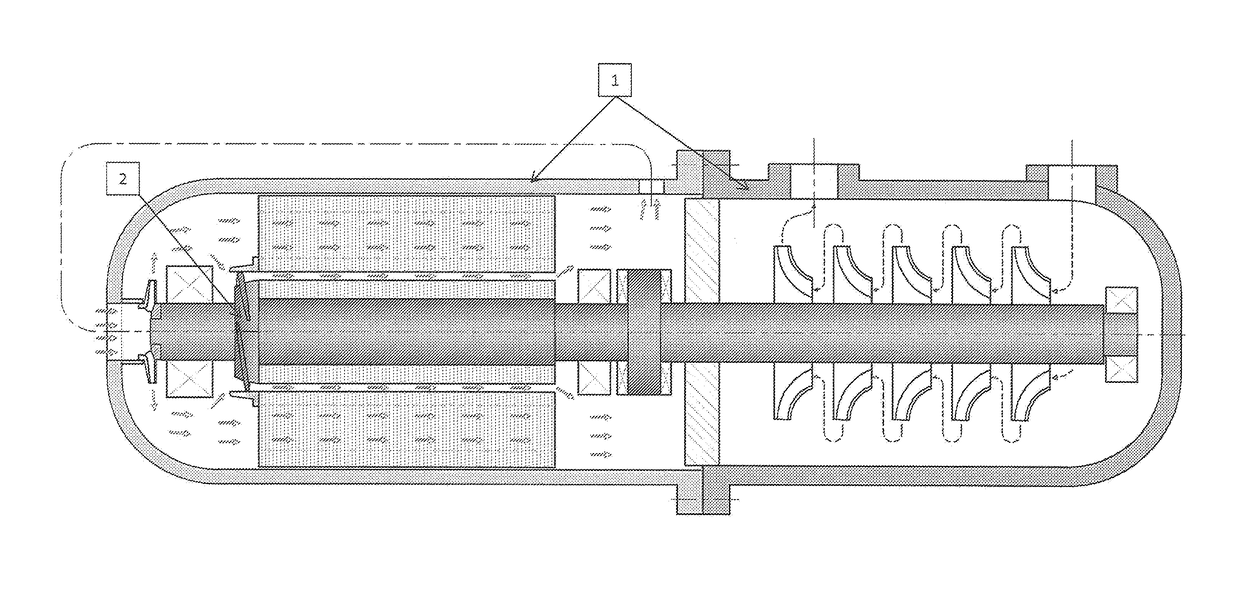
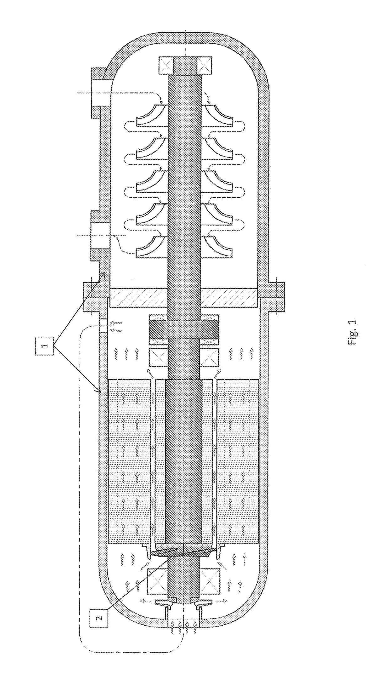
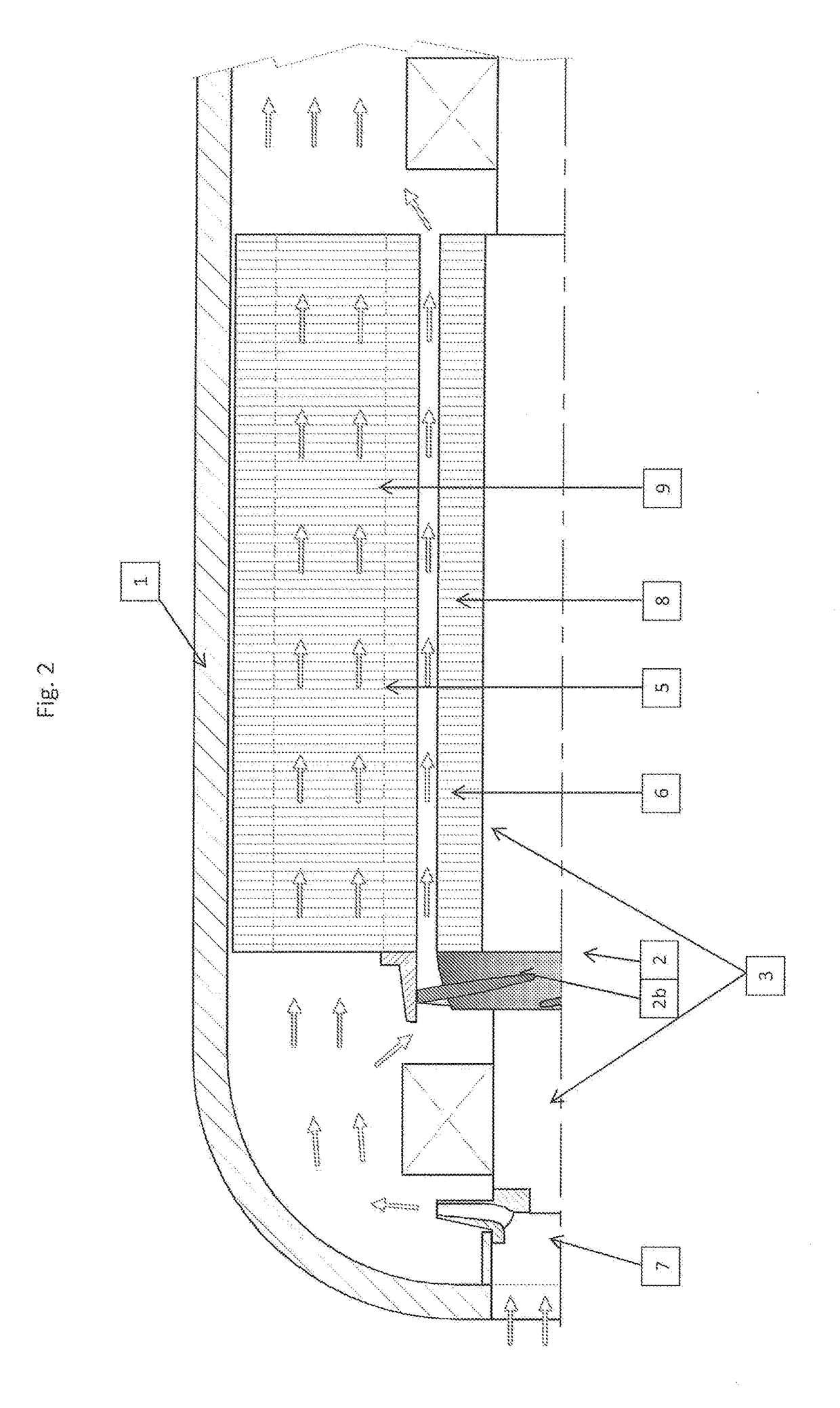
[0024]Reference is made to FIG. 1, illustrating, in longitudinal section, a subsea pressure booster 1 of the invention, with a combined balancing device and rotor stator gap circulation impeller 2. FIG. 2 illustrates the motor part of the subsea pressure booster of FIG. 1 in more detail. Accordingly, in the illustrated embodiment, the rotor stator gap coolant inlet pump is a combined impeller and balancing device. In some otherwise identical or similar embodiments, the rotor stator gap coolant inlet pump is not a combined impeller and balancing device. FIG. 2 illustrates the impeller 2 in detail, and it can be seen clearly that the impeller comprises a number of blades 2b. The impeller is fastened to the rotor 3 at the inlet of the rotor stator gap, as an axial extension of the rotor laminations / short circuit ring. The impeller has outer diameter just smaller than the outer diameter of the rotor stator gap, to ensure clearance at different temperatures. The outlet outer diameter of ...


PUM


Abstract

The invention provides a centrifugal pressure booster, for pressure boosting liquids, multiphase fluid or gas, the pres sure booster comprising a liquid filled electric motor with a stator and a rotor, with a rotor stator gap between the rotor and stator, a pressure boosting part in the form of a pump or compressor operatively coupled to the rotor, and at least one housing, one fluid inlet and one fluid outlet. The pressure booster is distinctive in that it comprises a rotor stator gap coolant inlet pump, for enhancing the coolant flow through the rotor stator gap. The invention also provides a related method and use of a rotor stator gap coolant inlet pump.

Description

FIELD OF THE INVENTION[0001]The invention relates to centrifugal pumps and compressors, for convenience also termed pressure boosters in this document. More specifically, the invention relates to improved cooling of a pressure booster, which enhances the maximum power and speed and prolong the service life of the pressure booster.BACKGROUND OF THE INVENTION AND PRIOR ART[0002]Improved cooling of pressure boosters, providing enhanced maximum power and speed and prolonged service life, is of general interest for users of pressure boosters, particularly users of subsea pressure boosters. However, numerous special challenges related to subsea pressure boosting limit the use. Subsea pressure boosting of liquids, multiphase fluid or gas is of great interest for the petroleum industry, due to the huge possibilities made available for the industry. Subsea pressure boosting can increase the production significantly from subsea wells, both the recovery and the production rate, and allow trans...

Claims


Application Information

Patent Timeline
IPC IPC(8): F04D29/58F04D13/06F04D29/62F04D25/06F04D29/42F04D1/00F04D17/08
CPCF04D29/5806F04D1/00F04D13/06F04D29/62F04D25/06F04D29/4206F04D29/426F04D17/08F04D13/0653F04D13/086F04D13/12F04D25/0606F04D25/0686F04D25/16F04D13/08F04D29/18H02K1/32H02K9/19
Inventor HOFSTAD, GEOLDERHEIM, TARJE
Owner AKER SOLUTIONS AS
Learn More