Automotive head up display

a head-up display and automotive technology, applied in optics, instruments, electrical equipment, etc., can solve the problems of easy shock damage, mechanical wear, and limited information for drivers, and achieve the effect of reducing the number of head-up displays and reducing the number of displays

Active Publication Date: 2017-09-14
SHARP KK
View PDF2 Cites 38 Cited by
  • Summary
  • Abstract
  • Description
  • Claims
  • Application Information

AI Technical Summary

Benefits of technology

[0092]Because the virtual image is formed by a single optical system, it exhibits all depth cues such as focus, binocular convergence, and motion parallax, making it comfortable for long term viewing. Continuously variable virtual image depth in the system allows the virtual image to be seamlessly integrated into the traffic scene.

Problems solved by technology

These mechanical systems suffer from mechanical wear over time and may easily suffer from shock damage if they are not mechanically isolated from the vehicle.
Further, the former system would only provide a cable image and hence can only display very limited information to the driver.
For the system to work, the lens would either need to be very thick, which would compromise its switching speed, or have very small Fresnel zone size, which would compromise its image quality.
This type of liquid crystal has not yet been utilized in mass display products, may not necessarily meet automotive standards, and may be expensive to be used in large volume production.
Such a system will have a very low optical efficiency, meaning the system will consume significant power to achieve high brightness required by automotive displays.
The system would also have a limited display contrast, which is a known limitation of liquid crystal display panels with ordinary backlights.
However, these systems are only capable of displaying images at discrete depth planes.
Since the screens can never be fully transparent, haze will become noticeable if the number of screens is increased in attempt to display a pseudo-continuous volumetric image.
The switchable reflectors are highly dependent on wavelength and angle of the incident light, making it unsuitable for full-color displays.
Currently there is no augmented reality technology that can achieve low haze, can be manufactured at a relatively low cost, and provide continuous volume augmented reality that uses readily-mass-manufacturable materials that fit automotive performance and safety standards.

Method used


Image

  • Automotive head up display
  • Automotive head up display
  • Automotive head up display

Examples


third embodiment

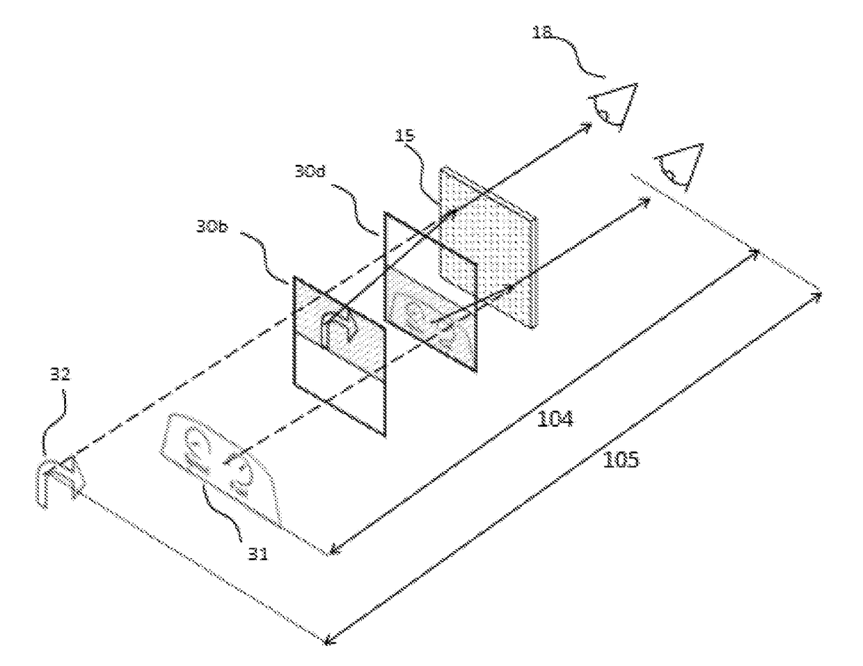
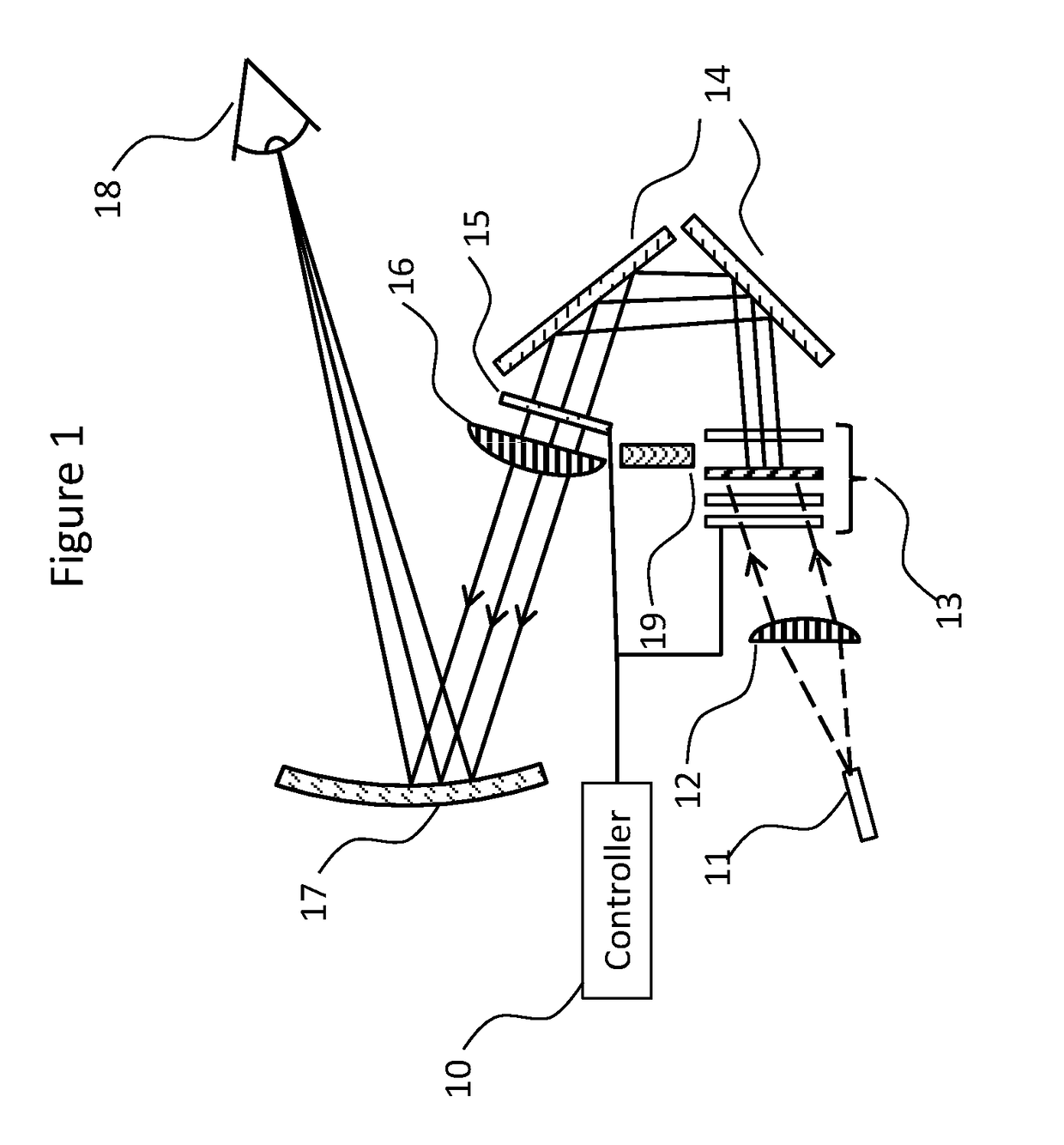
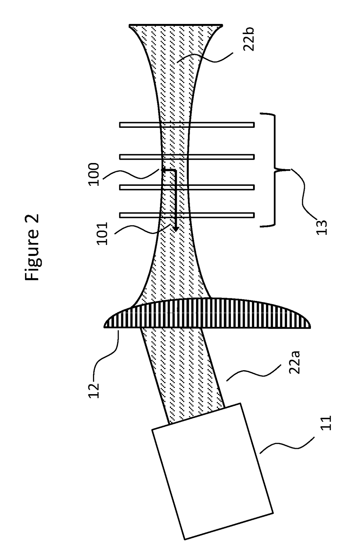
[0108]FIGS. 8a-8b illustrate a third embodiment that includes a laser projector 11, switchable projector screens 30a-30d (collectively referred to as switchable projector screen 30), and variable power lens 15. This embodiment differs from the main embodiment as the switchable projector screens 30 are pixelated or partitioned such that only a portion of the same screen can be switched diffusive at any given time (rather than the whole screen being switched uniformly diffusive or transparent). The material of the screen could be, but is not limited to, PDLC.

[0109]This system enables images 31, 32 to be perceived by a driver 18 at different depths 104, 105, where the images are displayed to the driver simultaneously without the need of temporally switching on and off different screens.

[0110]FIG. 9 is the same embodiment shown in FIGS. 8a-8b and illustrates how the system can benefit from spatial multiplexing by showing a dashboard image 31 in one screen's partition 30d and traffic inf...

fourth embodiment

[0111]FIG. 10 illustrates a fourth embodiment where the projector 11 is arranged to be physically closer to the screen 40d than all other screens (40a-c), where 40d represent the screen that is optically closest to the driver 18. In this embodiment, the virtual image comes from back scattered light from the switchable screens 40. The screens 40 can be made of known materials with a satisfactory backscattering efficiency such as Polymer Stabilized Cholesteric Texture (PSCT). The last screen 40a (i.e., the screen optically furthest from the driver 18) may be replaced by a permanent diffuser. This means if the screens are anti-reflection coated, there will be no need to use a beam block in the system.

first embodiment

[0112]In addition, one of the mirrors 14 from the first embodiment can be replaced by a partially transparent mirror or a beam splitter 41 to allow the projector's beam to reach the screens, but the mirror can also remain fully reflective if it is not obscuring the projector's light. This embodiment allows more flexibility in the folding up of the HUD system without potentially exposing the projector's exit pupil to the driver when none of the screens are fully diffusive at any instance.

[0113]FIG. 11 illustrates a fifth embodiment where a stack of switchable screens 50 is used instead of the screens 13 proposed in the first embodiment. When the screens 50 are in the transparent state, the polarization state of light transmitted through the screens is preserved (i.e., the polarization of the light passing through the screen is unaltered or altered by a small amount such that a specular beam transmitted through the polarizer 51 would be safe for the driver). This allows polarized ligh...


PUM


Abstract

A head-up-display (HUD) system includes at least one scanning laser projector operative to generate laser light, and a stacked array of multiple-switchable screens arranged relative to the projector to receive laser light generated by the projector, each screen of the stacked array of multiple-switchable screens spaced apart from one another and operative to switch between a transparent state and a diffusive state. A controller is operatively coupled to the stacked array of multiple-switchable screens, the controller configured to time sequentially switch each screen of the array from a transparent state to a diffusive state, wherein only one screen is switched to the diffusive state at any given time. An output of the projector is arranged at an angle or a distance from imaging optics succeeding the array of screens to prevent a specular beam emitted by the at least one scanning laser projector from intercepting the imaging optics succeeding the array of screens when all screens are in the transparent state.

Description

TECHNICAL FIELD[0001]The invention relates generally to automotive displays and, more particularly, to Head-Up-Displays (HUD) that provide enhanced driving safety.BACKGROUND ART[0002]Head-Up-Display (HUD) systems enable drivers to view crucial information without the need to look away from the road. Hence HUD systems have become an increasingly important component for automotive use to enhance road safety.[0003]Augmented Reality (AR), provides a three-dimensional (3D) viewing experience. A number of technologies have been developed to provide 3D AR, the most relevant of which are as follows:[0004]U.S. Pat. No. 8,521,411 B2 (Grabowski, Aug. 27, 2013) describes a HUD system that allows a continuous depth volumetric image by rapid mechanical scanning of a lens to re-image a laser beam into floating space. “Opt. Express 14, 12760-12769 (2006)” discloses a method of showing volumetric 3D images with a rapidly rotating mirror scanner to produce multiple slices of inclined images. These me...

Claims


Application Information

Patent Timeline
Patent Type & Authority Applications(United States)
IPC IPC(8): G02B27/01H04N13/00H04N13/04G09G3/00G06T19/00
CPCG02B27/0101G09G3/002G02B2027/0118H04N13/0429H04N13/004G06T19/006H04N2213/001H04N13/344H04N13/156H04N13/332
Inventor TAM, KA HOMONTGOMERY, DAVID JAMES
Owner SHARP KK
Why Eureka
Try Eureka