Spectral inversion detection for polarization-division multiplexed optical transmission

a technology of polarization division multiplexing and optical transmission, applied in optics, instruments, electrical equipment, etc., can solve the problems of unable to easily apply the approach in unable to guarantee the sign of the actual transfer function, and unable to meet the requirements of data-aided optical pdm transmission

Active Publication Date: 2017-09-14
XIEON NETWORKS SARL
View PDF15 Cites 10 Cited by
  • Summary
  • Abstract
  • Description
  • Claims
  • Application Information

AI Technical Summary

Benefits of technology

[0031]Herein, the control unit is preferably adapted to actually or virtually reverse the sign of the transfer function by effecting a complex conjugation of the output signal of one of the first or second DP-MZMs in the equivalent complex baseband. This complex conjugation can be carried out purely digitally, e.g. by inverting the sign of the driving signal of a quadrature component of one of the DP-MZMs, or by swapping the in-phase and quadrature components of the driving signals for one of the polarizations. This is an example of “virtually reversing” the sign of a transfer function, because the sign of the transfer function is not actually reversed, but the effect of the modification of the driving signal on the optical signal is the same as that of a sign change of a transfer function.

Problems solved by technology

However, due to the quadratical characteristics of the employed photo-detectors, these algorithms cannot discern between bias points with negative transfer function slope, such as bias point A in FIG. 2, and bias points with positive transfer function slope, as is the case for bias point B in FIG. 2, thereby leading to an uncertainty in the sign of the actual transfer function.
386-403, poses more difficult challenges.
However, for reasons explained in the following, this approach cannot be easily applied in data-aided optical PDM transmission, i.e. if the signal includes two polarization components carrying independent data.
The additional difficulty in PDM applications is due to the fact that data-aided channel estimation for PDM systems is preferably performed by means of mutually orthogonal training sequences transmitted over the H- and V-polarizations.
Although, in principle, orthogonality could be achieved by transmitting the training sequence on H while muting V and thereafter on V while muting H, this would not be bandwidth efficient and would also produce strong variations of the transmit power, which is detrimental in view of the nonlinearity of optical channels.
However, if one and only one polarization, i.e. H or V, is spectrally inverted, the orthogonality between the transmitted training sequences is lost.
This possible approach would hence require a backward channel from the receiver to the transmitter and suffers from a bootstrapping difficulty.

Method used


Image

  • Spectral inversion detection for polarization-division multiplexed optical transmission
  • Spectral inversion detection for polarization-division multiplexed optical transmission
  • Spectral inversion detection for polarization-division multiplexed optical transmission

Examples


Embodiment Construction

[0043]For the purposes of promoting an understanding of the principles of the invention, reference will now be made to the preferred embodiments illustrated in the drawings and specific language will be used to describe the same. It will nevertheless be understood that no limitation of the scope of the invention is thereby intended, such alterations and further modifications in the illustrated device and method and such further applications of the principles of the invention as illustrated therein being contemplated therein as would normally occur now or in the future to one skilled in the art to which the invention relates.

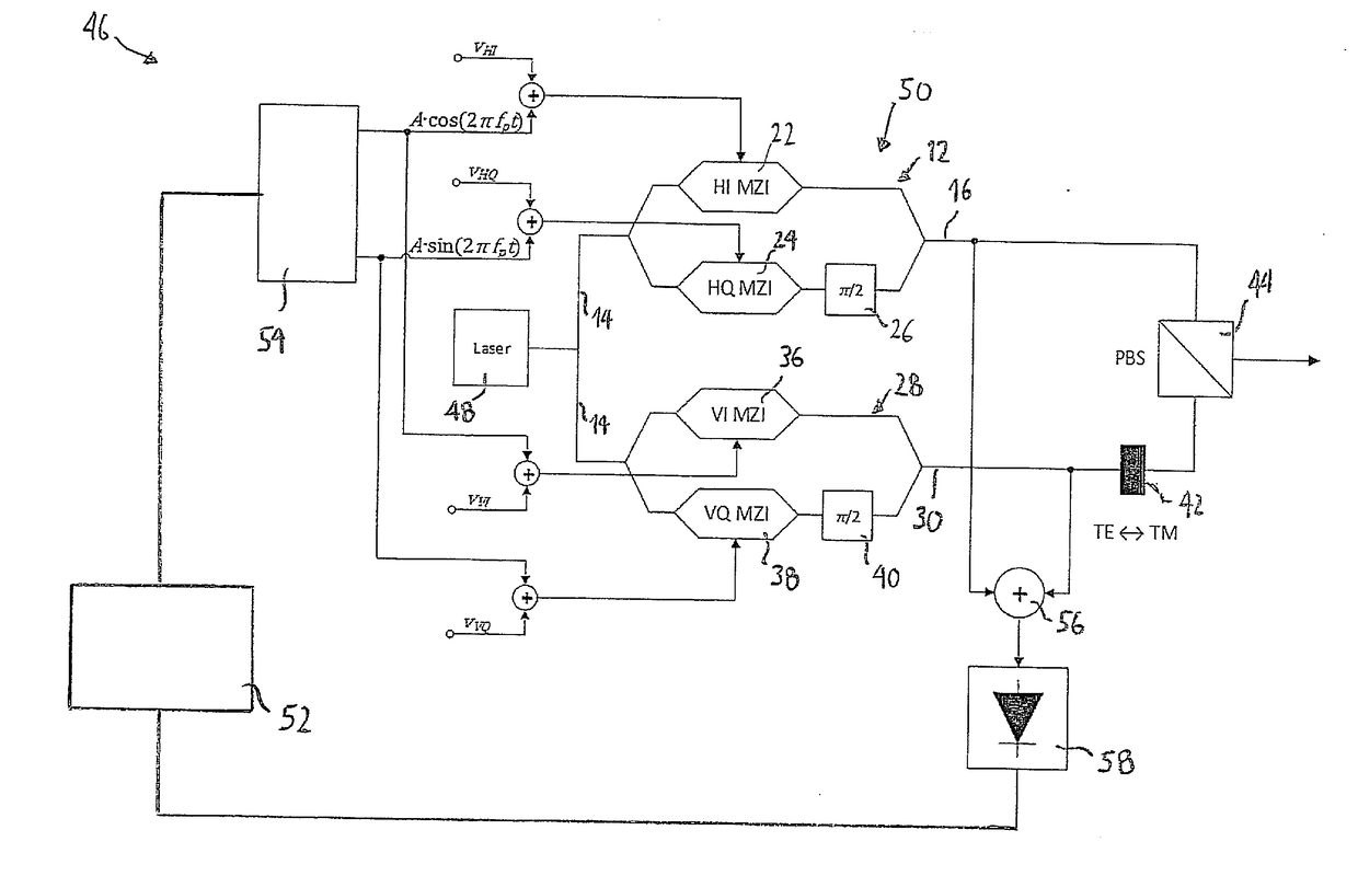
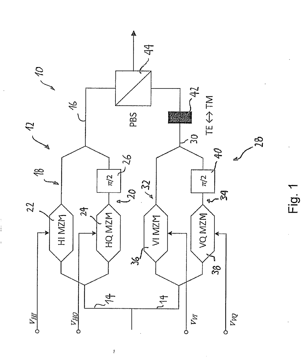
[0044]FIG. 3 shows a transmitter 46 according to an embodiment of the present invention. The transmitter comprises a laser 48, a modulator 50 and a control unit 52. The modulator 50 has generally a similar structure as the prior art modulator of FIG. 1, and likewise comprises first and second DP-MZMs 12, 28 as well as a TE / TM polarization conversion unit 42 and a...


PUM

PropertyMeasurementUnit
in-phaseaaaaaaaaaa
frequencyaaaaaaaaaa
frequenciesaaaaaaaaaa

Abstract

Disclosed herein is a modulator (50) for polarization-division multiplexing (PDM) transmission. The modulator (50) comprises first and second DP-MZMs (12, 28) associated with first and second polarizations, each DP-MZM (12, 28) having an input for an in-phase and a quadrature driving signal for modulating the in-phase and quadrature components of an optical signal according to respective transfer functions, and a detector (58) suitable for detecting light comprising at least a portion of the light outputted by the first DP-MZM (12) and a portion of the light outputted by the second DP-MZM (28). The modulator (50) is adapted to superimpose a first pilot signal on one of the in-phase and quadrature driving signals of the first DP-MZM (12) and on one of the in-phase and quadrature driving signals of the second DP-MZM (28), and a second pilot signal on the respective other of the in-phase and quadrature driving signals of the first and second DP-MZMs (12, 28). Further, the first and second pilot signals are chosen such that the signal detected by said detector (58) is indicative as to whether the slopes of the transfer functions are different for the in-phase and quadrature components of one of the first and second DP-MZMs (12, 28) and identical for the other of the first and second DP-MZMs (12, 28).

Description

FIELD OF THE INVENTION[0001]The present invention is in the field of optical data transport technology. More particularly, the present invention relates to a modulator for polarization-division multiplexing (PDM) transmission, an optical transmitter comprising said modulator and a method for controlling an optical transmitter.BACKGROUND OF THE INVENTION[0002]In FIG. 1, the structure of a conventional modulator 10 for polarization-division multiplexed (PDM) signals is shown. The modulator 10 of FIG. 1 is devised for PDM quadrature amplitude modulation (QAM). The modulator 10 comprises a first dual parallel Mach-Zehnder-modulator modulator (DP-MZM) 12, which comprises an input 14 for inputting an optical carrier, and an output 16 for outputting a QAM-modulated signal associated with a first polarization, which is referred to as “H-polarization” component in the following. Downstream of the optical in-put 14, the DP-MZM 12 branches into a first and a second arm 18, 20, respectively, th...

Claims


Application Information

Patent Timeline
Patent Type & Authority Applications(United States)
IPC IPC(8): H04J14/06H04B10/50G02F1/225
CPCH04J14/06G02F1/2255G02F2001/212G02F2201/58G02F2203/07H04B10/5053G02F1/0123H04B10/505H04B10/532H04B10/50572G02F1/212
Inventor CALABRO, STEFANOSPINNLER, BERNHARD
Owner XIEON NETWORKS SARL
Why Eureka
Try Eureka