Wearable food nutrition feedback system
a technology of nutrition feedback and wearable food, which is applied in the field of wearable food nutrition feedback system, can solve the problems of tedious tracking of consumption and nutritional information for each meal
- Summary
- Abstract
- Description
- Claims
- Application Information
AI Technical Summary
Benefits of technology
Problems solved by technology
Method used
Image
Examples
embodiment 300
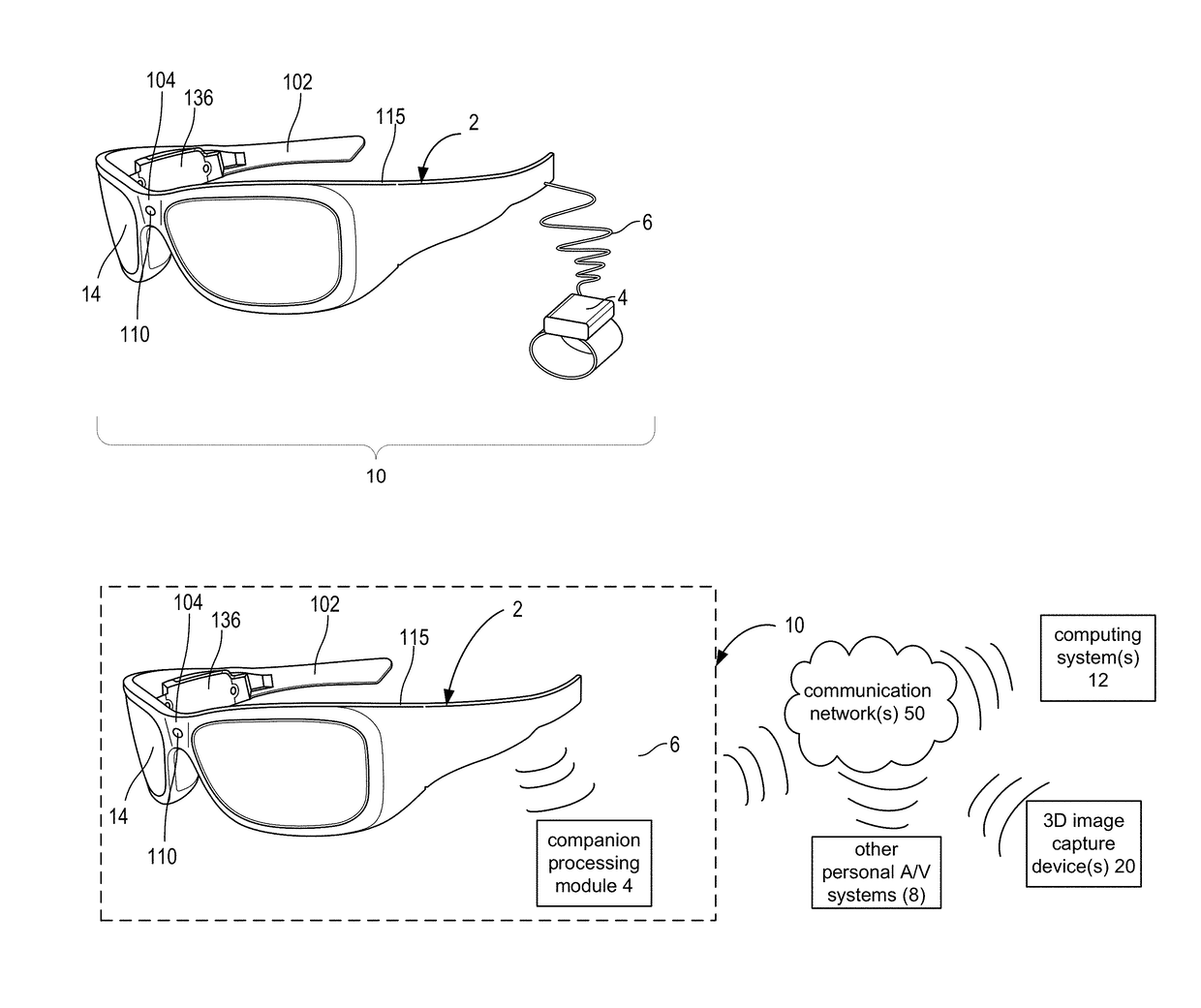
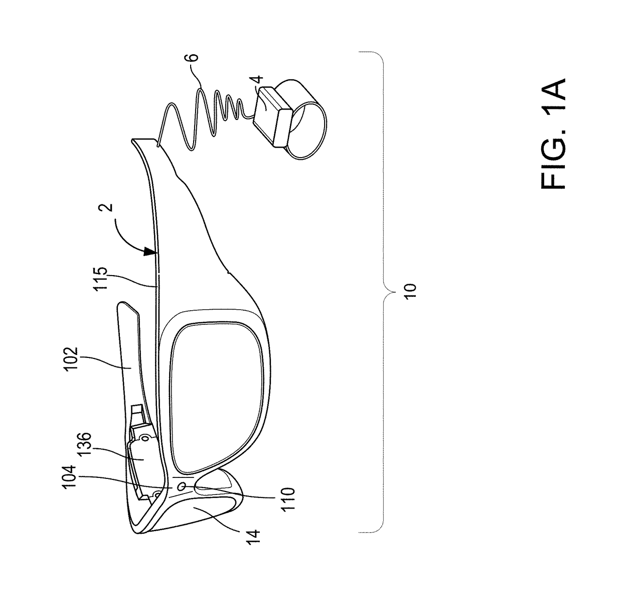
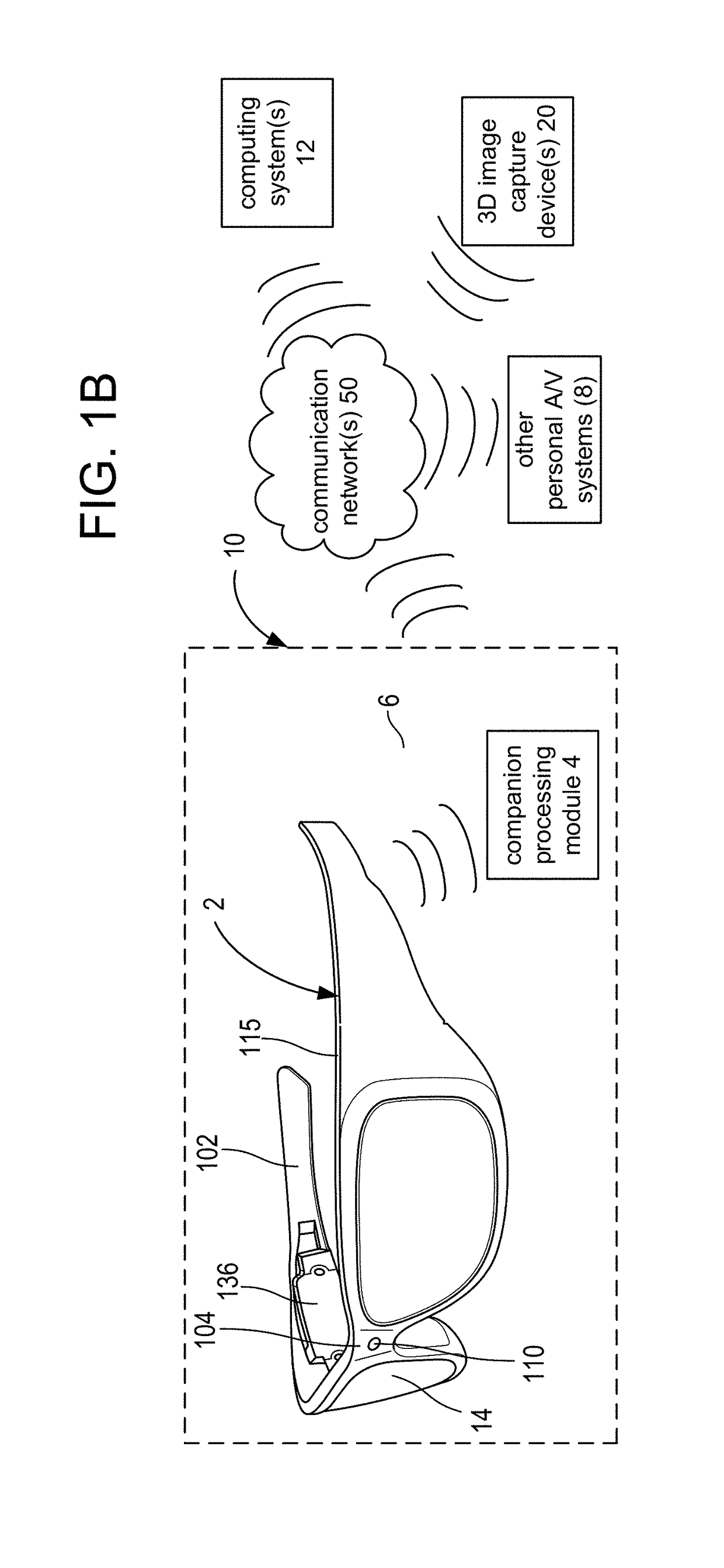
[0050]In general, FIG. 3A shows is a flowchart of a method embodiment 300 for aligning a see-through, near-eye, display with an IPD. In step 301, one or more processors of the control circuitry 136, automatically determines whether a see-through, near-eye, display device is aligned with an IPD of a wearer in accordance with an alignment criteria. If not, in step 302, the one or more processors cause adjustment of the display device by at least one display adjustment mechanism for bringing the device into alignment with the wearer IPD. If it is determined the see-through, near-eye, display device is in alignment with a wearer IPD, optionally, in step 303 an IPD data set is stored for the wearer. In some embodiments, a display device 2 may automatically determine whether there is IPD alignment every time anyone puts on the display device 2. However, as IPD data is generally fixed for adults, due to the confines of the human skull, an IPD data set may be determined typically once and s...
third embodiment
[0081]FIG. 5C is a top view of a movable display optical system of a see-through, near-eye, device including an arrangement of gaze detection elements. The display optical system 14 has a similar arrangement of gaze detection elements including IR illuminators 153 and photodetectors 152, and a light sensor 134r located on the frame 115 or lens 118 below or above optical axis 142. In this example, the display optical system 14 includes a light guide optical element 112 as the reflective element for directing the images into the wearer's eye and is situated between an additional see-through lens 116 and see-through lens 118. As reflecting element 124 is within the lightguide optical element and moves with the element 112, an embodiment of a microdisplay assembly 173 is attached on the temple 102 in this example to a display adjustment mechanism 203 for the display optical system 14 embodied as a set of three axis mechanism 203 with shafts 205 include at least one for moving the microd...
fourth embodiment
[0084]FIG. 5D is a top view of a movable display optical system of a see-through, near-eye, device including an arrangement of gaze detection elements. This embodiment is similar to FIG. 5C's embodiment including a light guide optical element 112. However, the only light detectors are the IR photodetectors 152, so this embodiment relies on glint detection only for gaze detection as discussed in the examples below.
[0085]In the embodiments of FIGS. 5A-5D, the positions of the gaze detection elements, e.g. the detection area 139 and the illuminators 153 and photodetectors 152 are fixed with respect to each other. In these examples, they are also fixed in relation to the optical axis of the display optical system 14.
[0086]In the embodiments above, the specific number of lenses shown are just examples. Other numbers and configurations of lenses operating on the same principles may be used. Additionally, in the examples above, only the right side of the see-through, near-eye, head mounted...
PUM
 Abstract
Description
Claims
Application Information
 - R&D
- Intellectual Property
- Life Sciences
- Materials
- Tech Scout
- Unparalleled Data Quality
- Higher Quality Content
- 60% Fewer Hallucinations
Browse by: Latest US Patents, China's latest patents, Technical Efficacy Thesaurus, Application Domain, Technology Topic, Popular Technical Reports.
© 2025 PatSnap. All rights reserved.Legal|Privacy policy|Modern Slavery Act Transparency Statement|Sitemap|About US| Contact US: help@patsnap.com


