

Shake-correction device and shake-correction method for photographing apparatus
- Summary
- Abstract
- Description
- Claims
- Application Information
AI Technical Summary
Benefits of technology
Problems solved by technology
Method used
Image

Examples
first embodiment
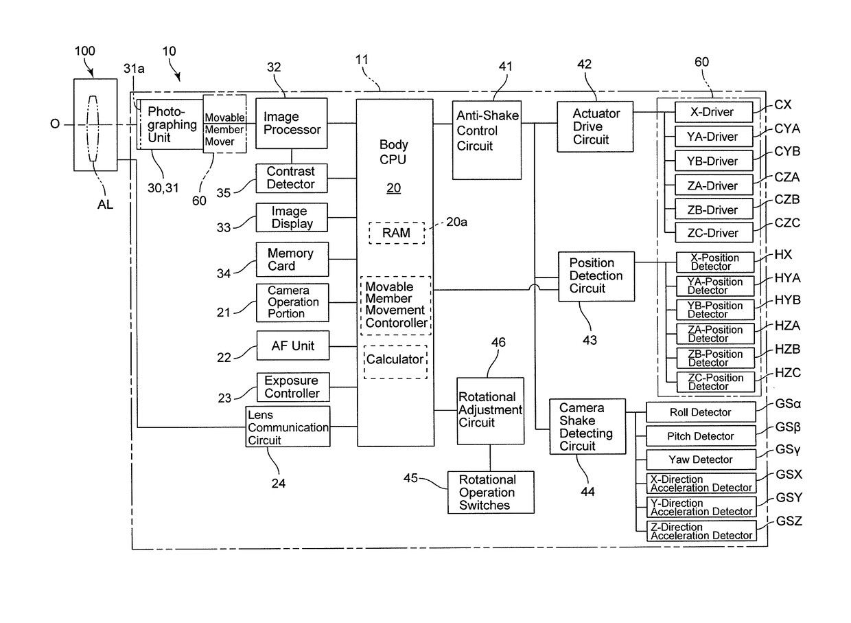
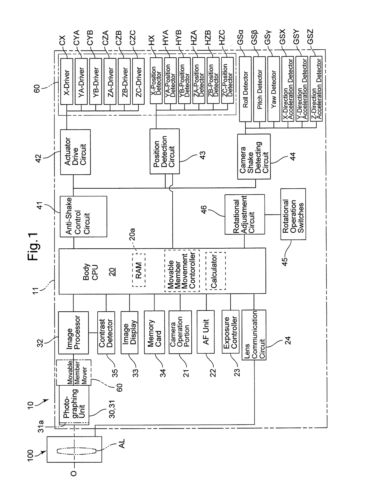
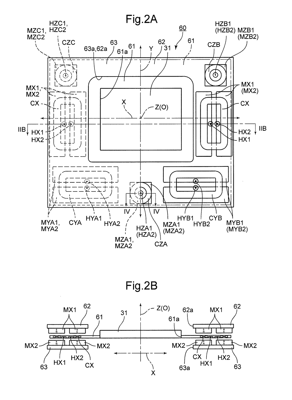
[0069]The stage apparatus 60 is further provided with three circular coils: a Z-drive coil (ZA-driver) CZA, a Z-drive coil (ZB-driver) CZB and a Z-drive coil (ZC-driver) CZC which are fixed to the movable stage 61. The Z-drive coil CZA is fixed at a position (middle position) between the pair of Y-drive coils CYA and CYB, and the Z-drive coils CZB and CZC are fixed above the pair of X-drive coils CX, respectively. The Z-drive coil CZA is arranged on the Y-axis, and the Z-drive coils CZB and CZC are arranged to be symmetrical with respect to the Y-axis (at equi-distant positions from the Y-axis). The center of gravity (the center of gravity of the whole) of the Z-drive coils CZA, CZB and CZC is substantially coincident with the center of gravity of the movable stage 61. It is desirable that the Z-drive coils CZA, CZB and CZC be arranged so that a line which connects two of the three Z-drive coils CZA, CZB and CZC extends parallel to one of the X-axis and the Y-axis and so that a line...
second embodiment
[0137]The above described embodiment relates to a shake-correction operation when the digital camera 10 is subjected to shake (hand-shake, vibrations, etc.) with the image sensor 31 at the initial state. In addition to the above-described embodiment, the present invention can also be applied to shake correction when the image sensor 31 is in a rotated state due to tilting, panning or rolling (turning). An example of a shake-correction operation, according the second embodiment, with the image sensor 31 in a tilted state will be described hereinbelow with reference to FIGS. 12 through 17.
[0138]FIG. 12 is a flowchart showing a shake correction operation, in a swing-and-tilt photographing state in which the image sensor 31 is tilted (rotated) about the X-direction, to correct angular shake, shift shake in the X and Y directions, and focusing direction shift shake. The difference between this second embodiment and the first embodiment of FIG. 6 is that in the first embodiment, the initi...
PUM
 Abstract
Description
Claims
Application Information