Monitoring system and monitoring method

a monitoring system and monitoring method technology, applied in the field of monitoring systems and monitoring methods, can solve the problems of difficult visual presentation, user difficulty, and difficulty in specific presentation of the volume of the sound as detailed visual information for sound, and achieve the effect of improving the detection process suppressing the deterioration of the detection accuracy of pilotless flying objects

Active Publication Date: 2017-09-28
PANASONIC INTELLECTUAL PROPERTY MANAGEMENT CO LTD
View PDF2 Cites 11 Cited by
  • Summary
  • Abstract
  • Description
  • Claims
  • Application Information

AI Technical Summary

Benefits of technology

[0008]The disclosure aims to suppress deterioration of the detection accuracy of a pilotless flying object and to improve a detection process of a pilotless flying

Problems solved by technology

However, when a pilotless flying object such as a drone is detected, if audio detection is performed by setting all directions in the monitoring area as a monitoring target, from the perspective of a non-directional microphone, a direction in which a frequency of a loud sound being generated is high cannot be set as a masking area.
Therefore, in a case where a loud sound is detected in the monitoring area, an object in a direction of the masking area, which is different from a pilotless flying object originally desired to be detected, may be erroneously detected as a target pilotless flying object.
In a monitoring camera which changes an imaging direction in order to perform imaging by focusing on the detected flying object, it is

Method used


Image

  • Monitoring system and monitoring method
  • Monitoring system and monitoring method
  • Monitoring system and monitoring method

Examples


second exemplary embodiment

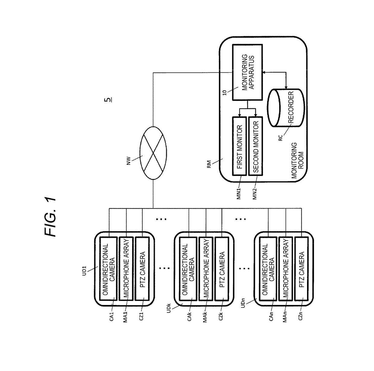
[0174]In the second exemplary embodiment, since the internal configuration of each device configuring pilotless flying object detection system 5 is the same as the internal configuration of each device configuring pilotless flying object detection system 5 according to the first exemplary embodiment, the same reference numeral is assigned to the same contents and the description of the same contents is not repeated, and different contents will be described.

[0175]In the second exemplary embodiment, after generating and displaying the sound pressure heat map on first monitor MN1 described in the first exemplary embodiment, monitoring apparatus 10 analyzes in detail, the sound pressure heat map according to the relationship between the calculated value of the sound pressure which is required for generating the sound pressure heat map and a plurality of thresholds (refer to later description) and displays the result, through the user's operation with respect to console 32 (refer to late...

third exemplary embodiment

[0217]In the third exemplary embodiment, since the internal configuration of each device configuring pilotless flying object detection system 5 is the same as the internal configuration of each device configuring pilotless flying object detection system 5 according to the first exemplary embodiment, the same reference numeral is assigned to the same contents and the description of the same contents is not repeated, and different contents will be described.

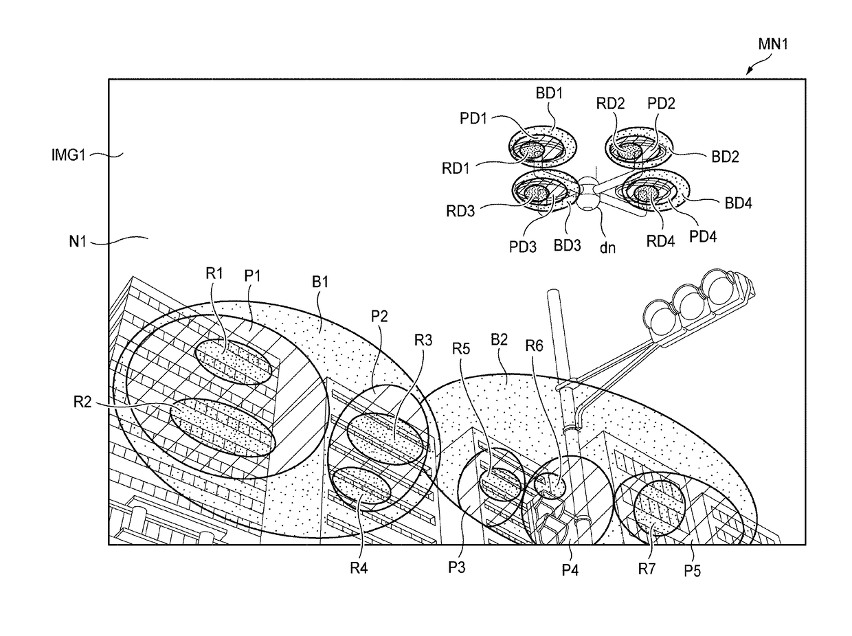
[0218]In the third exemplary embodiment, monitoring apparatus 10 generates a translucent sound pressure heat map as a translucent image (translucent map) of a sound pressure heat map after generating the sound pressure heat map (sound parameter map) described in the first exemplary embodiment, and superimposes the translucent sound pressure heat map onto the omnidirectional image to display the result on first monitor MN1 (refer to FIG. 22). FIG. 22 is an explanatory diagram illustrating an outline of an overlay display of the omni...


PUM


Abstract

In a pilotless flying object detection system, a masking area setter sets a masking area to be excluded from detection of a pilotless flying object which appears in a captured image of a monitoring area, based on audio collected by a microphone array. An object detector detects the pilotless flying object based on the audio collected by the microphone array and the masking area set by the masking area setter. An output controller superimpose sound source visual information, which indicates the volume of a sound at a sound source position, at the sound source position of the pilotless flying object in the captured image and displays the result on a first monitor in a case where the pilotless flying object is detected in an area other than the masking area.

Description

BACKGROUND[0001]1. Technical Field[0002]The present disclosure relates to a monitoring system and a monitoring method which monitor an imaging area of a camera device in which, for example, a pilotless flying object flies.[0003]2. Description of the Related Art[0004]A flying object monitoring apparatus depicted in Japanese Patent Unexamined Publication No. 2006-168421 is capable of detecting the presence of an object and the flight direction of the object using a plurality of audio detectors which detect sounds generated in a monitoring area on a per-direction basis. If a processor of the flying object monitoring apparatus detects the flight and the flight direction of a flying object through audio detection using microphones, the processor causes a monitoring camera to face the direction in which the flying object flies. Furthermore, the processor displays a video which is captured by the monitoring camera on a display device.[0005]However, when a pilotless flying object such as a ...

Claims


Application Information

Patent Timeline
IPC IPC(8): H04N7/18H04R29/00G10L21/10H04R1/40
CPCH04N7/183G10L21/10H04R29/005H04R1/406G01H9/002G01S5/20G08G5/0082G08G5/0026G08G5/0069H04R3/005H04R2420/07H04R2430/20G06V20/52G06V20/17
Inventor MATSUMOTO, HIROYUKIYOSHIKUNI, SHINTAROMIYAMOTO, MASANARI
Owner PANASONIC INTELLECTUAL PROPERTY MANAGEMENT CO LTD
Why Eureka
Try Eureka