Cooling device, control method and control program for same, and storage medium
- Summary
- Abstract
- Description
- Claims
- Application Information
AI Technical Summary
Benefits of technology
Problems solved by technology
Method used
Image
Examples
first exemplary embodiment
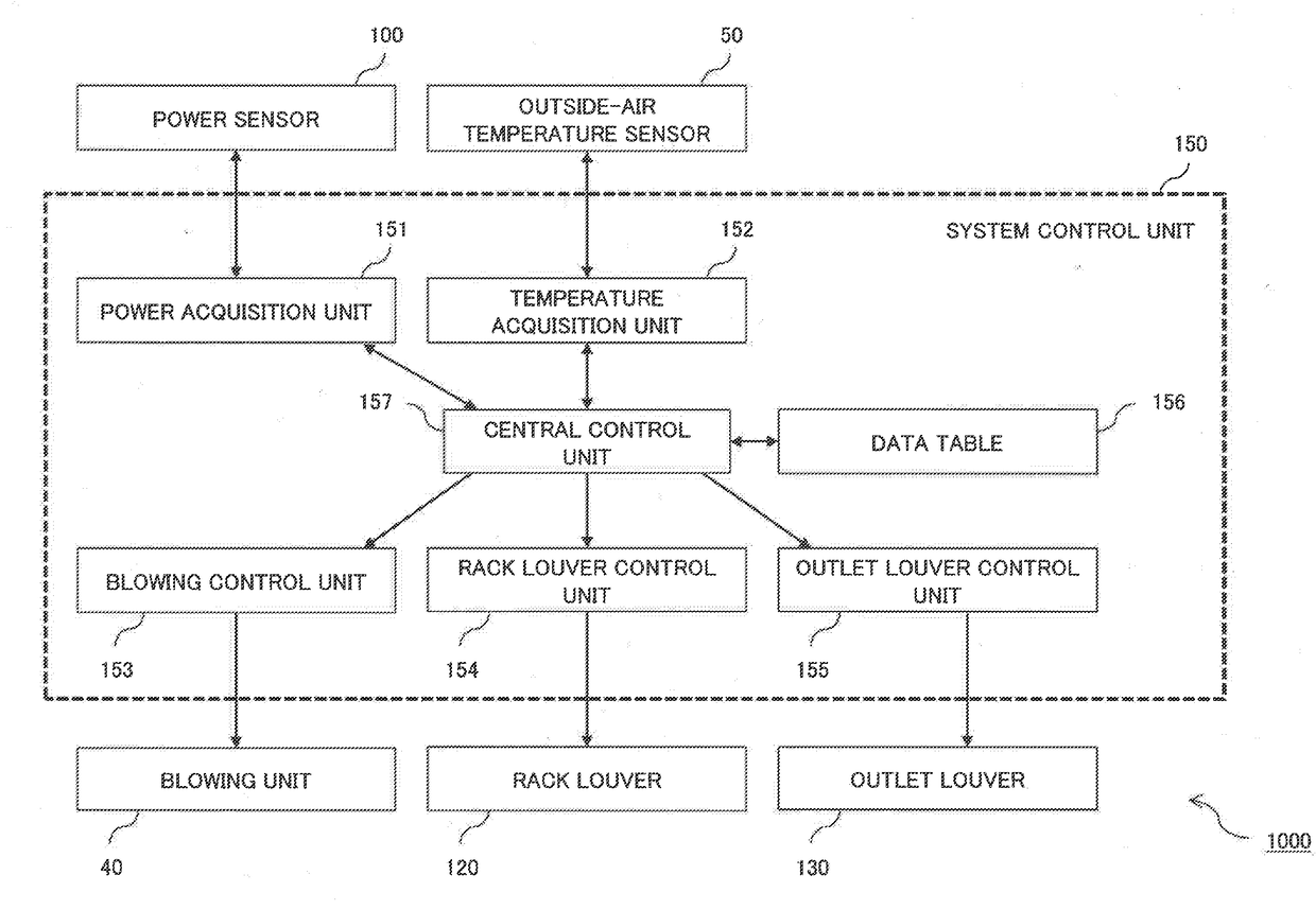
[0039]A configuration of a cooling device 1000 according to a first exemplary embodiment of the present invention will be described.
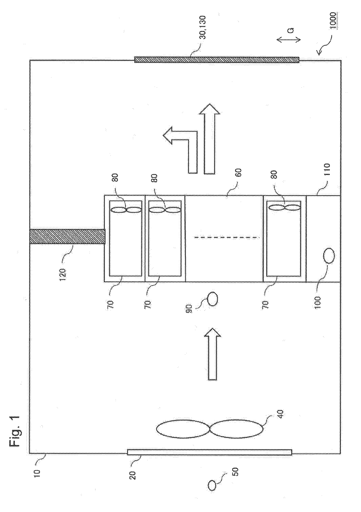
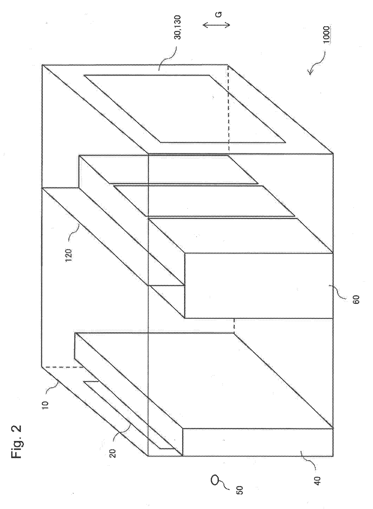
[0040]FIG. 1 is a cross-sectional view illustrating a configuration of the cooling device 1000. FIG. 2 is a transparent perspective view transparently illustrating a configuration of the cooling device 1000. A vertical direction G is illustrated in FIGS. 1 and 2.
[0041]As illustrated in FIGS. 1 and 2, the cooling device 1000 includes an enclosure 10, an inlet 20, an outlet 30, a blowing unit 40, an outside-air temperature sensor 50, a rack 60, electronic equipment 70, an electronic equipment fan 80, a rack inlet temperature sensor 90, a power sensor 100, an electronic equipment accessory 110, a rack louver 120, and an outlet louver 130. The cooling device 1000 is also called a module-type data center. The rack 60 corresponds to the electronic equipment housing enclosure according to the present invention. The rack louver 120 corresponds to the first open...
second exemplary embodiment
[0141]A configuration of a cooling device 1000A according to a second exemplary embodiment of the present invention will be described.
[0142]FIG. 7 is a cross-sectional view illustrating the configuration of the cooling device 1000A. FIG. 8 is a transparent perspective view transparently illustrating the configuration of the cooling device 1000A. A vertical direction G is illustrated in FIGS. 7 and 8. In FIGS. 7 and 8, a component equivalent to each component illustrated in FIGS. 1 to 6 is given a reference sign equivalent to the reference sign given in FIGS. 1 to 6.
[0143]As illustrated in FIGS. 7 and 8, the cooling device 1000A includes an enclosure 10, an inlet 20, an outlet 30, a blowing unit 40, a rack 60, an electronic equipment 70, an electronic equipment fan 80, a rack inlet temperature sensor 90, a power sensor 100, an electronic equipment accessory 110, a rack louver 120, an outlet louver 130, a vaporizing-type cooling unit 160, an outside-air temperature-humidity sensor 170...
third exemplary embodiment
[0195]A configuration of a cooling device 1000B according to a third exemplary embodiment of the present invention will be described.
[0196]FIG. 11 is a cross-sectional view illustrating the configuration of the cooling device 1000B. FIG. 12 is a transparent perspective view transparently illustrating the configuration of the cooling device 1000B. A vertical direction G is illustrated in FIGS. 11 and 12. In FIGS. 11 and 12, a component equivalent to each component illustrated in FIGS. 1 to 10 is given a reference sign equivalent to the reference sign given in FIGS. 1 to 10.
[0197]As illustrated in FIGS. 11 and 12, the cooling device 1000B includes an enclosure 10, an inlet 20, an outlet 30, a rack 60, an electronic equipment 70, an electronic equipment fan 80, a rack inlet temperature sensor 90, a power sensor 100, an electronic equipment accessory 110, a rack louver 120, an outlet louver 130, a vaporizing-type cooling unit 160, an outside-air temperature-humidity sensor 170, and an i...
PUM
 Abstract
Description
Claims
Application Information
 - R&D
- Intellectual Property
- Life Sciences
- Materials
- Tech Scout
- Unparalleled Data Quality
- Higher Quality Content
- 60% Fewer Hallucinations
Browse by: Latest US Patents, China's latest patents, Technical Efficacy Thesaurus, Application Domain, Technology Topic, Popular Technical Reports.
© 2025 PatSnap. All rights reserved.Legal|Privacy policy|Modern Slavery Act Transparency Statement|Sitemap|About US| Contact US: help@patsnap.com


