
Raised Bed Garden and Micro Greenhouse System

a greenhouse system and raised bed technology, applied in the field of raised bed garden and micro greenhouse system, can solve the problems of difficult construction of beds, limited life span of wooden beds, and increased labor intensity of workers, and achieve the effect of optimizing manufacturing cycle time and cost, and facilitating insertion and alignment of connectors

Inactive Publication Date: 2017-10-05
PETTY ERIC HAYES
View PDF7 Cites 6 Cited by
  • Summary
  • Abstract
  • Description
  • Claims
  • Application Information

AI Technical Summary

Benefits of technology

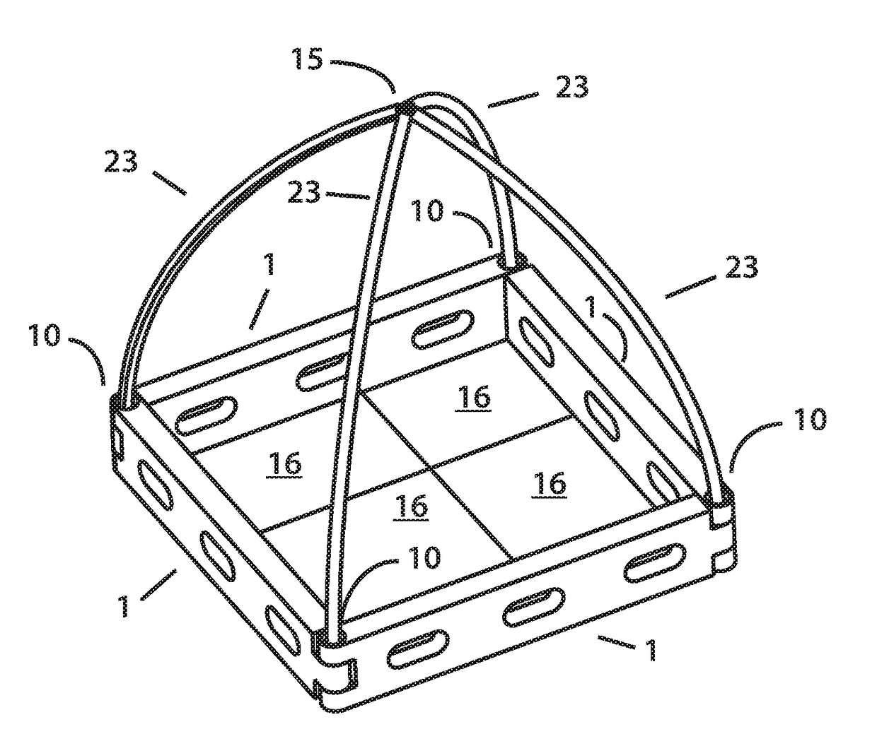
The patent describes a raised bed garden system that consists of rails and connectors that can be easily combined to create raised bed gardens or sandboxes of various sizes and heights. The garden includes insulation and a heater to maintain the soil at the proper temperature regardless of the season. Different structural frameworks can be inserted into the connectors to allow the garden to be covered with materials that protect against cold, hail, deer, or insects. The rails used in the garden can be easily inserted and aligned using blow molding, optimizing manufacturing cycle time and cost. The technical effects of this invention include improved soil health, consistent shape and easy addition of additional parts, as well as a more efficient and cost-effective manufacturing process.

Problems solved by technology

Wooden beds have a limited life span, as the wood eventually rots and becomes unusable.
Stone or brick are sometimes used, but these beds are difficult to construct and more difficult to move.

Method used


Image

  • Raised Bed Garden and Micro Greenhouse System
  • Raised Bed Garden and Micro Greenhouse System
  • Raised Bed Garden and Micro Greenhouse System

Examples


Embodiment Construction

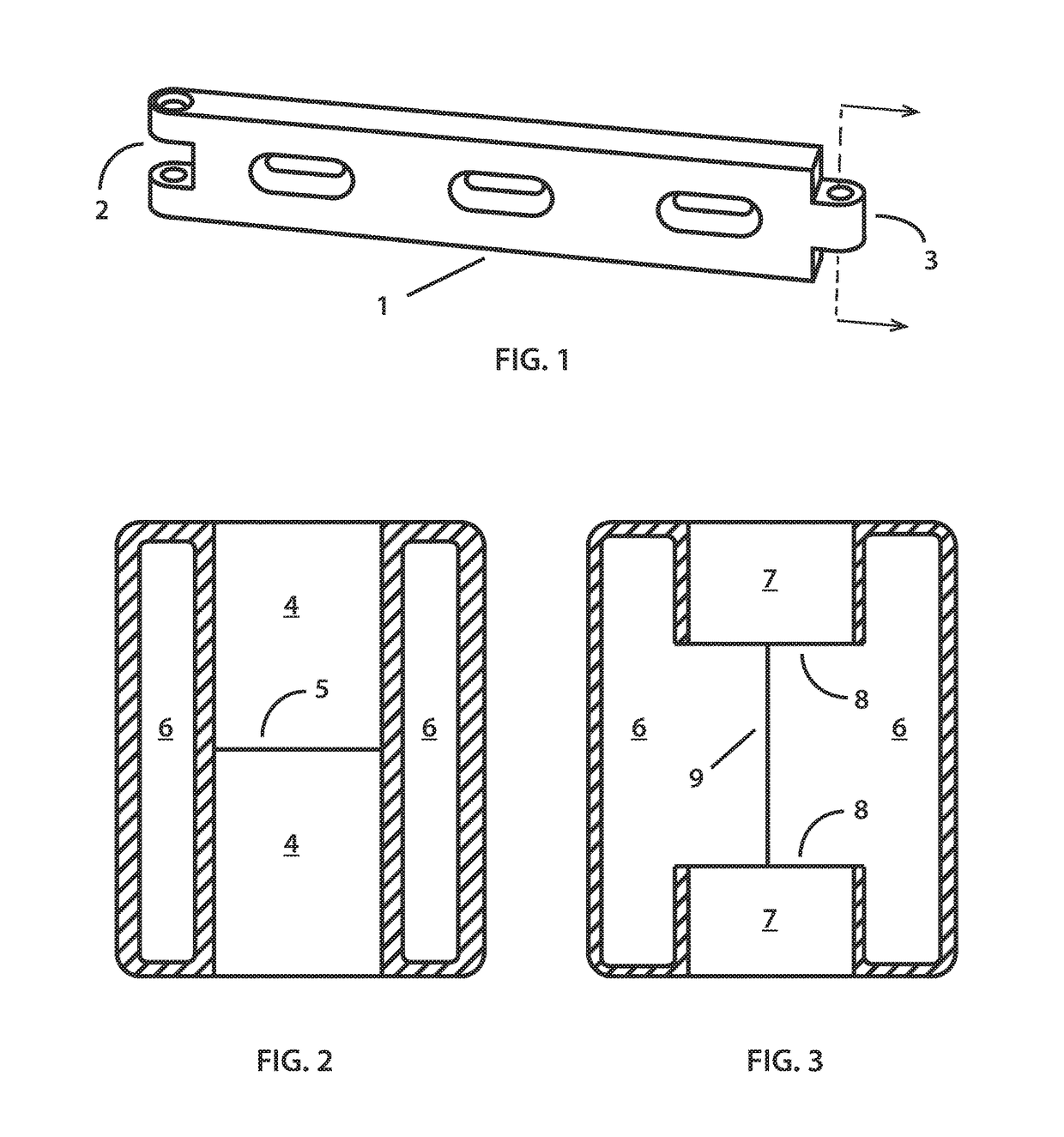
[0027]FIG. 1 is a perspective view of a raised bed garden rail 1. It has a male end 3 and a female end 2 which allow the rails to be connected end-to-end and the combined rails to form any angle between 90 and 270 degrees.

[0028]FIG. 2 shows a cross-sectional view of the male end 3 of rail 1. A bushing 4 is constructed in the rail 1 by use of a secondary action in the mold. After the mold closes on the parison and air is blown into the parison two cylinders are activated and move to form the bushing 4. The cylinders meet at the action parting line 5. The inside surface 6 of the outer wall of the rail 1 is visible in the section. After blow molding rail 1 the flashing at the parting line 5 is removed with a hole saw to create a single bushing that passes all the way through the male end 3 of rail 1.

[0029]Similar actions are used at the female end 2 of rail 1 to form bushings during the blow molding, and the flashing later removed with a hole saw.

[0030]The bushings allow a tight and ea...


PUM

PropertyMeasurementUnit
angleaaaaaaaaaa
angleaaaaaaaaaa
shapeaaaaaaaaaa

Abstract

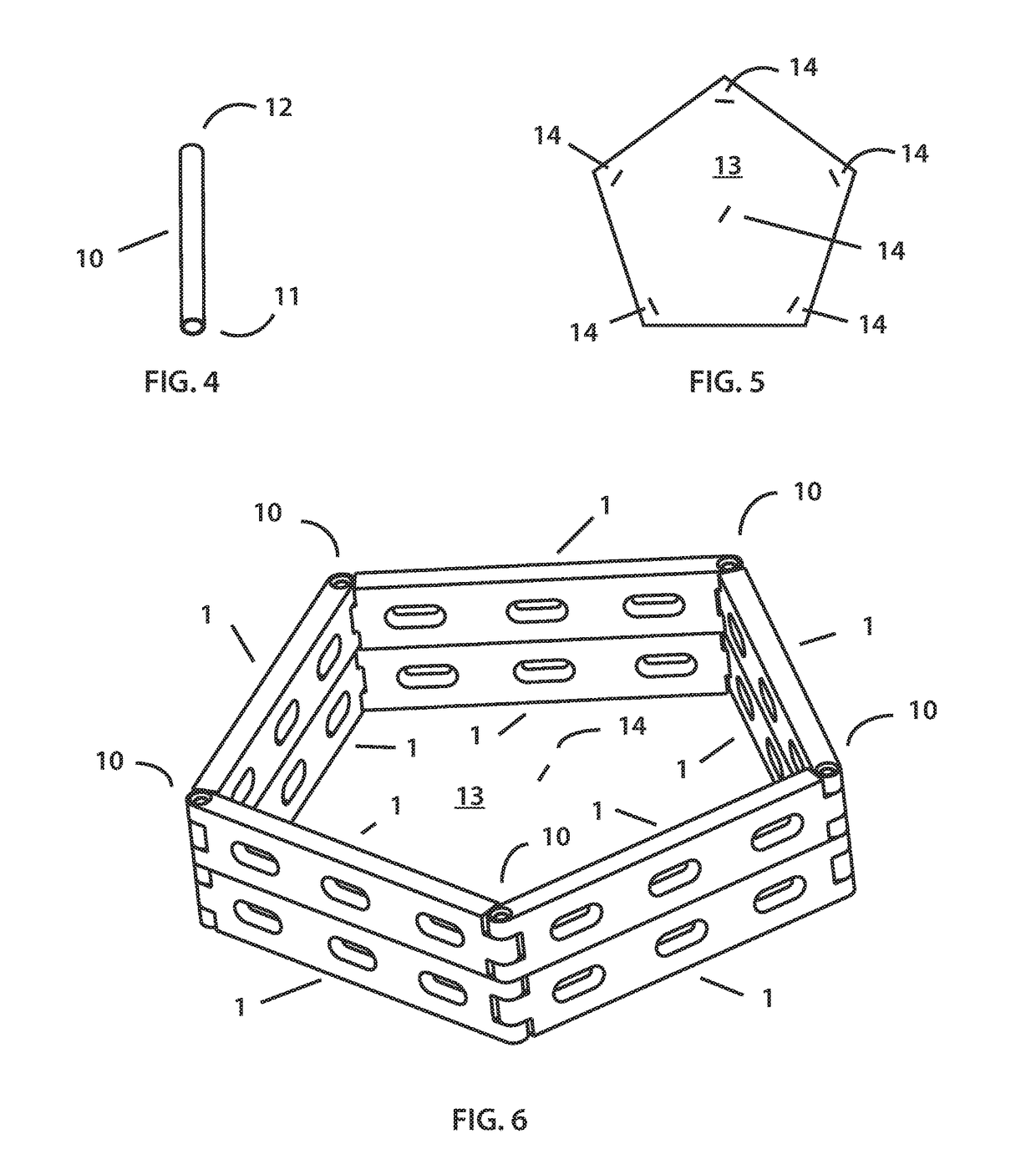
A raised bed garden and sandbox system comprised of rails and connectors, where the rails are connected to each other via a hinge-like system and joined by the insertion of tubular connectors that are circular in cross-section and open at one end to allow the insertion of a framework for a cover. A structure to support a cover is described, consisting of multiple cross-members, where one end of each cross-member is inserted into a connector and the other end of the cross-member is inserted into the opposite connector. An alternative design for a structure to support a cover is described, where for each cross-member one end is inserted into a connector and the other end is inserted into a central hub. A pattern is described to ensure that the raised bed garden or sandbox is arranged into a regular polygon. A heating element consisting of an electrical resistor arranged in a plane is described, as well as an planar insulator sized to fit the raised bed garden. An improvement in the design of a blow-molded rail provides higher quality and shorter cycle time by forming a partial bushing in the male end of the rail instead of a full bushing.

Description

CROSS-REFERENCE TO RELATED APPLICATIONS[0001]I claim under 35 U.S.C. §119(e) the benefit of the previously filed provisional application RAISED BED GARDEN AND MICRO GREENHOUSE SYSTEM, U.S. 62 / 315,188 filed on Mar. 30, 2016.STATEMENT REGARDING FEDERALLY SPONSORED RESEARCH OR DEVELOPMENT[0002]Not Applicable.REFERENCE TO SEQUENCE LISTING, A TABLE, OR A COMPUTER PROGRAM LISTING COMPACT DISC APPENDIX[0003]Not Applicable.BACKGROUND OF THE INVENTION[0004]Raised bed gardens have been used for centuries as a method to achieve higher yields while utilizing the same amount of gardening space. Historically, raised beds have typically been made of wood, stone, or man-made materials such as cinder blocks, resulting in raised beds which are time-consuming and difficult to construct. Additionally, raised beds made of wood have a very limited lifetime.[0005]Cold frames and hot houses have been used to extend gardening seasons by providing a covered environment for plants, but these systems are typic...

Claims


Application Information

Patent Timeline
Patent Type & Authority Applications(United States)
IPC IPC(8): A01G9/10A01G9/26A01G9/12A01G9/16B29C49/48A01G9/02A63H33/32A01G9/14
CPCA01G9/10A63H33/32A01G9/26A01G9/1407A01G9/1438B29L2031/7006B29C49/4802A01G9/026A01G9/12B29C2049/4807B29K2023/06A01G9/16B29C49/0031Y02A40/25A01G9/029
Inventor PETTY, ERIC HAYES
Owner PETTY ERIC HAYES
Learn More