Smoking device and method for aerosol-generation

a technology of smoke-generating devices and aerosols, which is applied in the direction of liquid spraying apparatus, tobacco, food science, etc., can solve the problems of reducing the sensitivity of the system to ambient temperature fluctuations, many atomizers require relatively high power, and inability to atomize relatively viscous liquids, etc., to achieve reliable and repeatable fashion, simple design, and relatively low cost

Active Publication Date: 2017-10-05
AKRIA CLIENT SERVICES LLC
View PDF5 Cites 87 Cited by
  • Summary
  • Abstract
  • Description
  • Claims
  • Application Information

AI Technical Summary

Benefits of technology

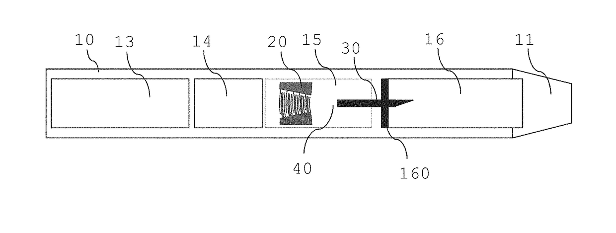
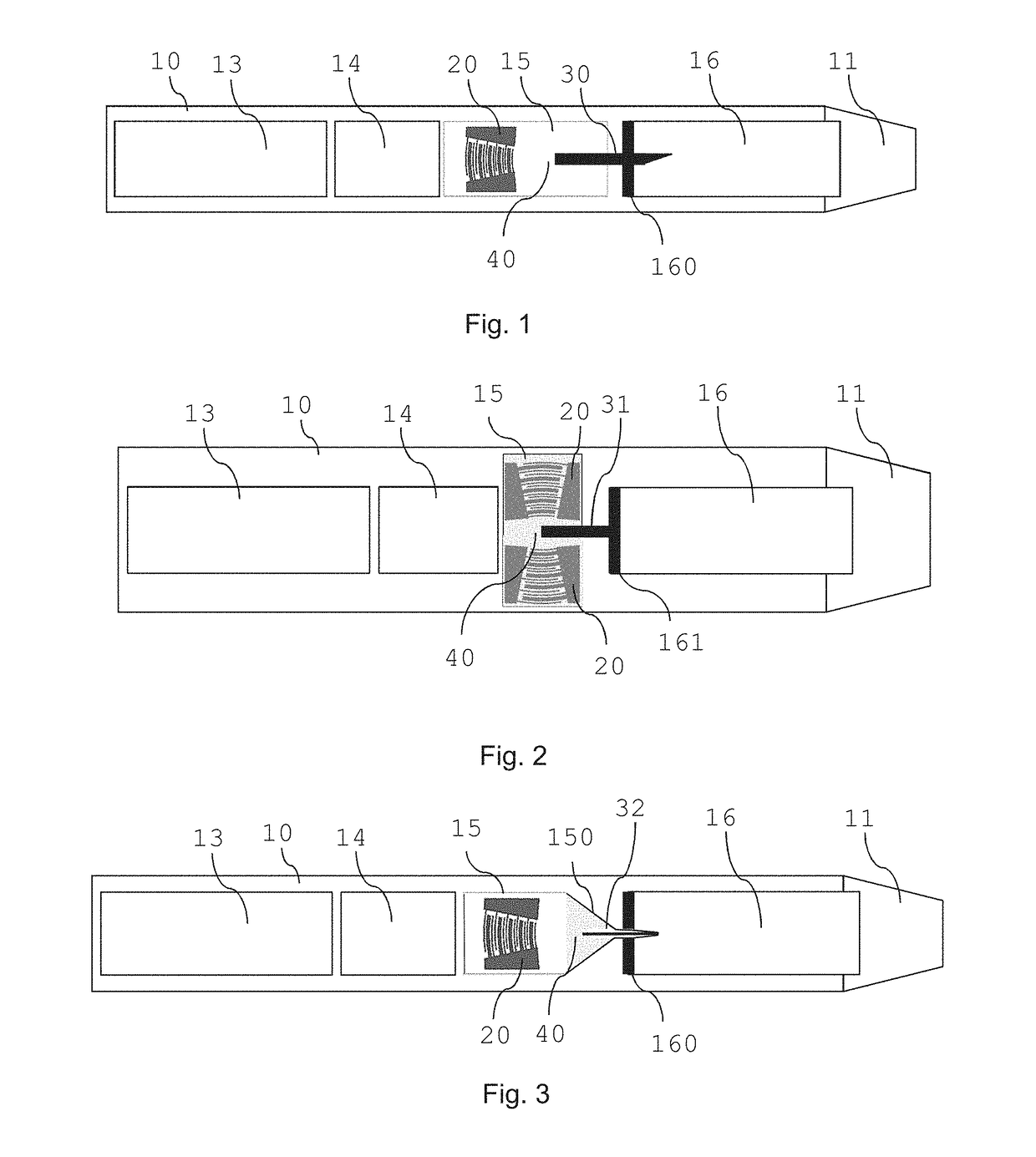
[0006]This manner of generating aerosol can provide a more reliable and consistent amount of aerosol from a liquid aerosol-forming substrate. In addition, such aerosol generation requires less power than when generated with known vibration elements, for example those using solely heat.
[0061]A cartridge comprising a supply element and an SAW-atomizer allows for a new atomization process each time a cartridge is replaced. Deposits or residues in the supply element and / or on the SAW-atomizer may be removed upon replacing a cartridge. The SAW-atomizer including a supply element may also be reusable and fixedly mounted elements of the smoking device. With this configuration, waste and material cost may be reduced.

Problems solved by technology

A problem with many atomizers using ultrasonic vibrations is that they are not able to atomize relatively viscous liquids, such as those typically used in electrically operated smoking systems.
In addition, many atomizers require relatively high power to achieve a desired atomization rate.
This may reduce the sensitivity of the system to fluctuations in ambient temperature.
A size of the heater may also be limited to the size of an atomization region.
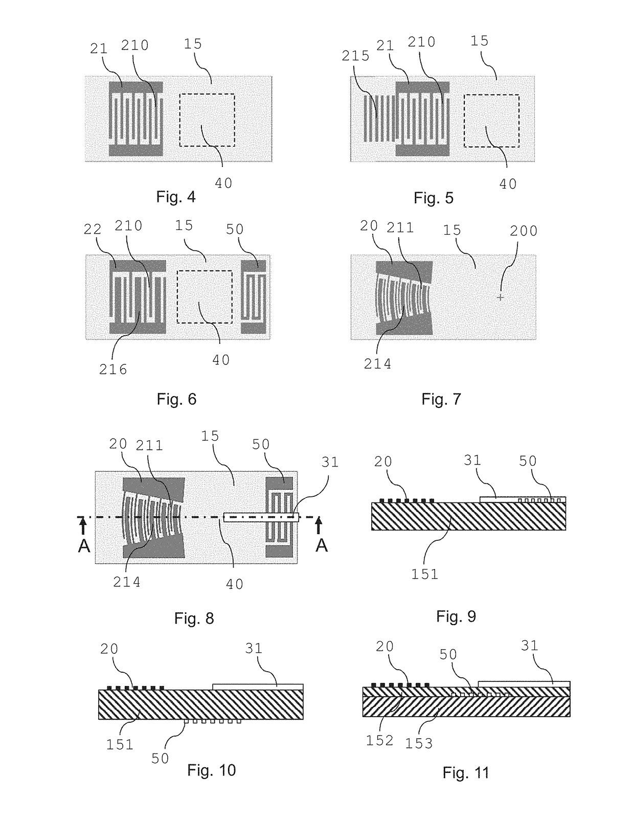
More than one input transducer may generate surface acoustic waves to interfere with each other (e.g., positive interference to enhance an energy input into the atomization region).

Method used


Image

  • Smoking device and method for aerosol-generation
  • Smoking device and method for aerosol-generation
  • Smoking device and method for aerosol-generation

Examples


Embodiment Construction

[0092]It should be understood that when an element or layer is referred to as being “on,”“connected to,”“coupled to,” or “covering” another element or layer, it may be directly on, connected to, coupled to, or covering the other element or layer or intervening elements or layers may be present. In contrast, when an element is referred to as being “directly on,”“directly connected to,” or “directly coupled to” another element or layer, there are no intervening elements or layers present. Like numbers refer to like elements throughout the specification. As used herein, the term “and / or” includes any and all combinations of one or more of the associated listed items.

[0093]It should be understood that, although the terms first, second, third, etc. may be used herein to describe various elements, components, regions, layers and / or sections, these elements, components, regions, layers, and / or sections should not be limited by these terms. These terms are only used to distinguish one eleme...


PUM


Abstract

A smoking device for aerosol-generation may comprise a device housing, a surface acoustic wave-atomizer (SAW-atomizer), a supply element, and a control system. The device housing may include a storage portion for an aerosol-forming substrate. The SAW-atomizer may include an atomization region, a first transducer, and / or a second transducer. The first transducer is configured to generate first surface acoustic waves that propagate along a surface of the SAW-atomizer. The supply element is arranged to supply the aerosol-forming substrate from the storage portion to the atomization region of the SAW-atomizer. The control system is configured to operate the SAW-atomizer to atomize the aerosol-forming substrate in the atomization region to generate an aerosol. A cartridge for such a smoking device and a method for generating an aerosol in a smoking system are also provided.

Description

CROSS-REFERENCE TO RELATED APPLICATIONS[0001]This is a continuation of and claims priority to PCT / EP2017 / 054668, filed on Feb. 28, 2017, and further claims priority to EP 16162973.8, filed on Mar. 30, 2016, both of which are hereby incorporated by reference in their entirety.BACKGROUNDField[0002]Example embodiments relate to smoking devices, methods, and smoking systems for the aerosol generation of an aerosol-forming substrate, and cartridges for such smoking devices. The smoking device and aerosol-generating system are electrically operated devices and systems.Description of Related Art[0003]In electrically operated smoking systems for example, a liquid aerosol-forming substrate is atomized to form an aerosol. Typically, in atomizers, a coil of heater wire is wound around an elongate wick that is soaked in a liquid aerosol-forming substrate. Other types of atomizers use ultrasonic vibrations, rather than heat, to atomize a liquid substrate. In such devices, vibrations are used to ...

Claims


Application Information

Patent Timeline
Patent Type & Authority Applications(United States)
IPC IPC(8): A24F47/00B05B17/06A24F40/05A24F40/10
CPCA24F47/008B05B17/0661B05B17/0684B05B17/0669B05B17/0607A24F40/05A24F40/10A24F40/46A24F40/44
Inventor COURBAT, JEROME CHRISTIANMIRONOV, OLEG
Owner AKRIA CLIENT SERVICES LLC
Why Eureka
Try Eureka