Portable qpcr and qrt-pcr apparatus
a qpcr and pcr technology, applied in the field of qpcr and pcr qpcr portable devices, can solve the problems of significant testing time and interference with the accuracy of pcr product quantification, and achieve the effect of saving reaction time and apparatus siz
- Summary
- Abstract
- Description
- Claims
- Application Information
AI Technical Summary
Benefits of technology
Problems solved by technology
Method used
Image
Examples
embodiment 1
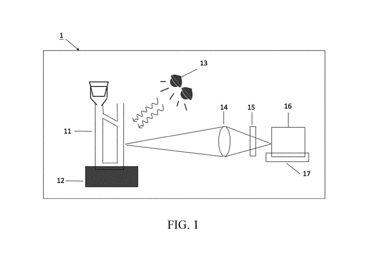
[0040]As illustrated in FIG. 1, the q-PCR and qRT-PCR device 1 comprises a temperature controlling unit, which is a heat source and a temperature sensor 12 in this embodiment, and a circulation-enabling container, which is a U-shaped loop 11 in this embodiment. A light source 13, a photo-detector 16, a filter 15, a lens 14, and a processor 17 are also shown in the FIG. 1.
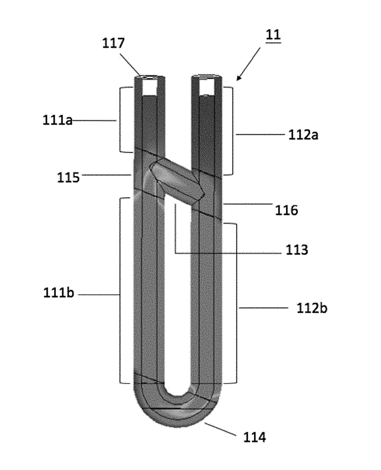
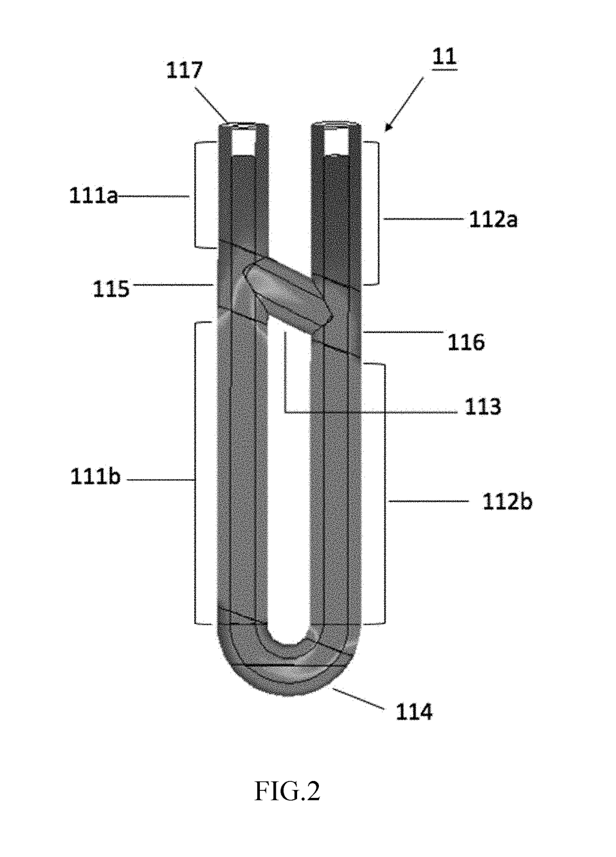
[0041]As shown in FIG. 2, the asymmetric circulation-enabling container is a U-shaped loop 11 with a pathway at different vertical height between the two ends of the U-shaped loop 11 forming a loop pathway. The U-shaped loop 11 has a left zone 111, a right zone 112, a link zone 113, and a bottom zone 114. The left and right zone 111,112 are perpendicular to the ground, and there is an opening 117 on the top of the left zone 111. The link zone 113 is connecting the left and right zone 111, 112 with a predetermined angle. In this embodiment, the left end of the link zone 113 is higher than the right end thereof. Furth...
embodiment 2
[0048]Referring to FIG. 4 and FIG. 5, a q-PCR and qRT-PCR apparatus 2 includes a temperature controlling unit, that is a heat source and a temperature sensor 22 in this embodiment, and a circulation-enabling container, which is U-shaped loop 21. A light source 23, a photo-detector 26, a lens 24, a filter 25, and a processor 27 are also shown in the FIG. 4 and FIG. 5. The connection and region of the light source 23, the photo-detector 26, the lens 24, the filter 25, and the processor 27 are substantially the same as described in FIG. 1. However, the connection and the region of the U-shaped loop 21 and the heat source and a temperature sensor 22 are different from FIG. 1.
[0049]When the heat source and a temperature sensor 22 provide heat to the U-shaped loop 21, the asymmetric structure of the U-shaped loop 21 is capable of allowing a solution therein to flow in a uni-directional way and form a flow field. As shown in FIG. 5, the U-shaped loop 21 has a left zone 211, a right zone 21...
embodiment 3
[0052]Referring to FIG. 6 and FIG. 7, a q-PCR and qRT-PCR apparatus 3 includes two sets of temperature controlling units, that are heat sources and temperature sensors 32a and 32b in this embodiment, a circulation-enabling container, that is U-shaped loop 31, a light source 33, a photo-detector 36, a lens 34, a filter 35, and a processor 37. The connection and region of the light source 33, the photo-detector 36, the lens 34, the filter 35, and the processor 37 are substantially the same as described in FIG. 1. However, the connection and the region of the U-shaped loop 31 and the heat sources and temperature sensors 32a and 32b are different from FIG. 1.
[0053]The heat sources and temperature sensors 32a and 32b could be defined as relatively higher heat source and temperature sensor 32a and relatively lower heat source and temperature sensor 32b. The preferred placement of both is the height of the relatively higher heat source and temperature sensor 32a being lower than the height...
PUM
| Property | Measurement | Unit |
|---|---|---|
| total volume | aaaaa | aaaaa |
| inner diameter | aaaaa | aaaaa |
| circulation speed | aaaaa | aaaaa |
Abstract
Description
Claims
Application Information
 - R&D
- Intellectual Property
- Life Sciences
- Materials
- Tech Scout
- Unparalleled Data Quality
- Higher Quality Content
- 60% Fewer Hallucinations
Browse by: Latest US Patents, China's latest patents, Technical Efficacy Thesaurus, Application Domain, Technology Topic, Popular Technical Reports.
© 2025 PatSnap. All rights reserved.Legal|Privacy policy|Modern Slavery Act Transparency Statement|Sitemap|About US| Contact US: help@patsnap.com


