Eureka AIR delivers breakthrough ideas for toughest innovation challenges, trusted by R&D personnel around the world.

Individual vessel utilized for cleaning, lubricating and sterilizing devices for heat sterilizer

Inactive Publication Date: 2017-10-05
OVERMYER THAD J +1
View PDF2 Cites 0 Cited by
  • Summary
  • Abstract
  • Description
  • Claims
  • Application Information

AI Technical Summary

Benefits of technology

The patent describes a device that is heated to sterilize it. After the heating cycle is complete, the device is placed on its base and the solution it was in drains out of the device. The heat from the heated device helps to dry it out. The technical effect of this invention is that it provides a convenient and efficient way to sterilize and dry devices.

Problems solved by technology

The heat sterilization process of a device affects the life span of the device.
When the device is exposed to body fluids or sources of contaminates, the device requires cleaning and possibly lubrication of the device prior to sterilization.
When a device is not cleaned properly, contaminates remaining on the device will create a build up of sterilized layers of contaminates.
This build up of contaminates may affect the function, sterilization efficiency and the life span of the device.
These products can affect the flow of the steam and therefore prevent the proper sterilization process.
All of these devices are exposed to contamination such as the patient's body fluids, saliva, blood, tooth structure particles, restorative material particles, material for cleaning teeth, bone spicules, polishing burrs containing grit and rubber particles.
When the contra angle is exposed to contaminates, this allows the internal gears or bearing mechanisms of these angles to be contaminated.
Although the handpiece parts such as O-rings, bearings, impeller or turbine are enclosed in a canister type housing, the high-speed rotation of the impeller or the turbine creates a centrifugal force to cause contaminates to be brought into these internal handpiece parts.
Over a period of time without proper cleaning and lubrication of these devices, the life span of the device's moving parts are affected by the build up of contaminates and the heat sterilizing of these contaminates.
Materials such as oral fluids, blood, tooth structure, filling material structures, or bone spicules sucked into the internal parts lead to failure of the handpiece.
These materials can be detrimental to the life span of the turbine.
The lubricant within the handpiece tubing (drive line) may impede the penetration of the steam from the heat sterilizer, as the lubricant and steam are not miscible.
This creates improper sterilization of the area.
This gooey material builds up within the handpiece's internal parts and affects the life span of the handpiece.
The automated cleaning lubrication device may fail without the operator's knowledge.

Method used


Image

  • Individual vessel utilized for cleaning, lubricating and sterilizing devices for heat sterilizer
  • Individual vessel utilized for cleaning, lubricating and sterilizing devices for heat sterilizer
  • Individual vessel utilized for cleaning, lubricating and sterilizing devices for heat sterilizer

Examples


Embodiment Construction

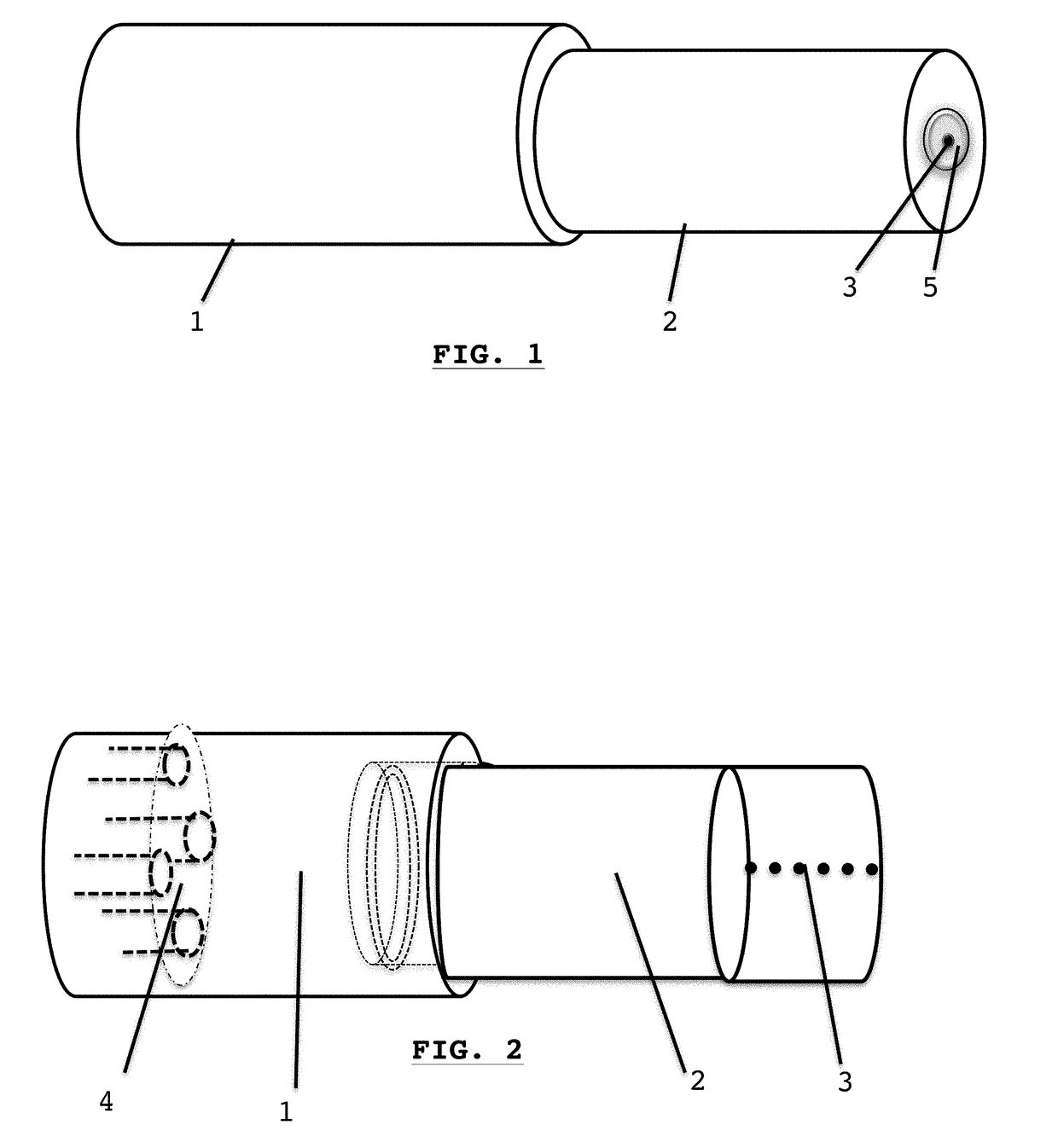
[0034]FIG. 1 illustrates a two-piece cylinder shaped vessel: the base 1 and the top 2 of the vessel. The end of the top 2 has a depressed area 5 with an opening from the conduit 3. The base 1 is larger in dimension than the top 2. This vessel will be used to contain a solution and devices that need cleaning, lubricating and sterilizing.

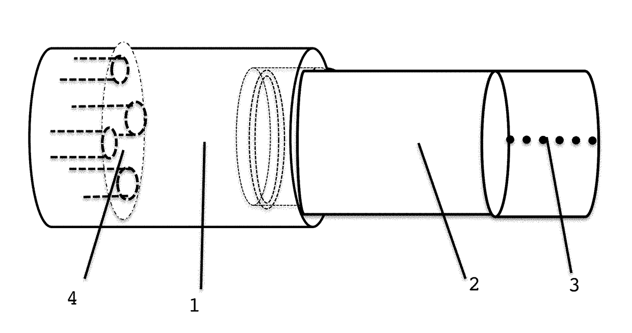
[0035]FIG. 2 shows the internal view of the vessel. The base 1 has female threads and the top 2 has male threads. A reservoir 4 is within the base 1. The top 2 has a threaded conduit 3 which will hold a pressure relief valve.

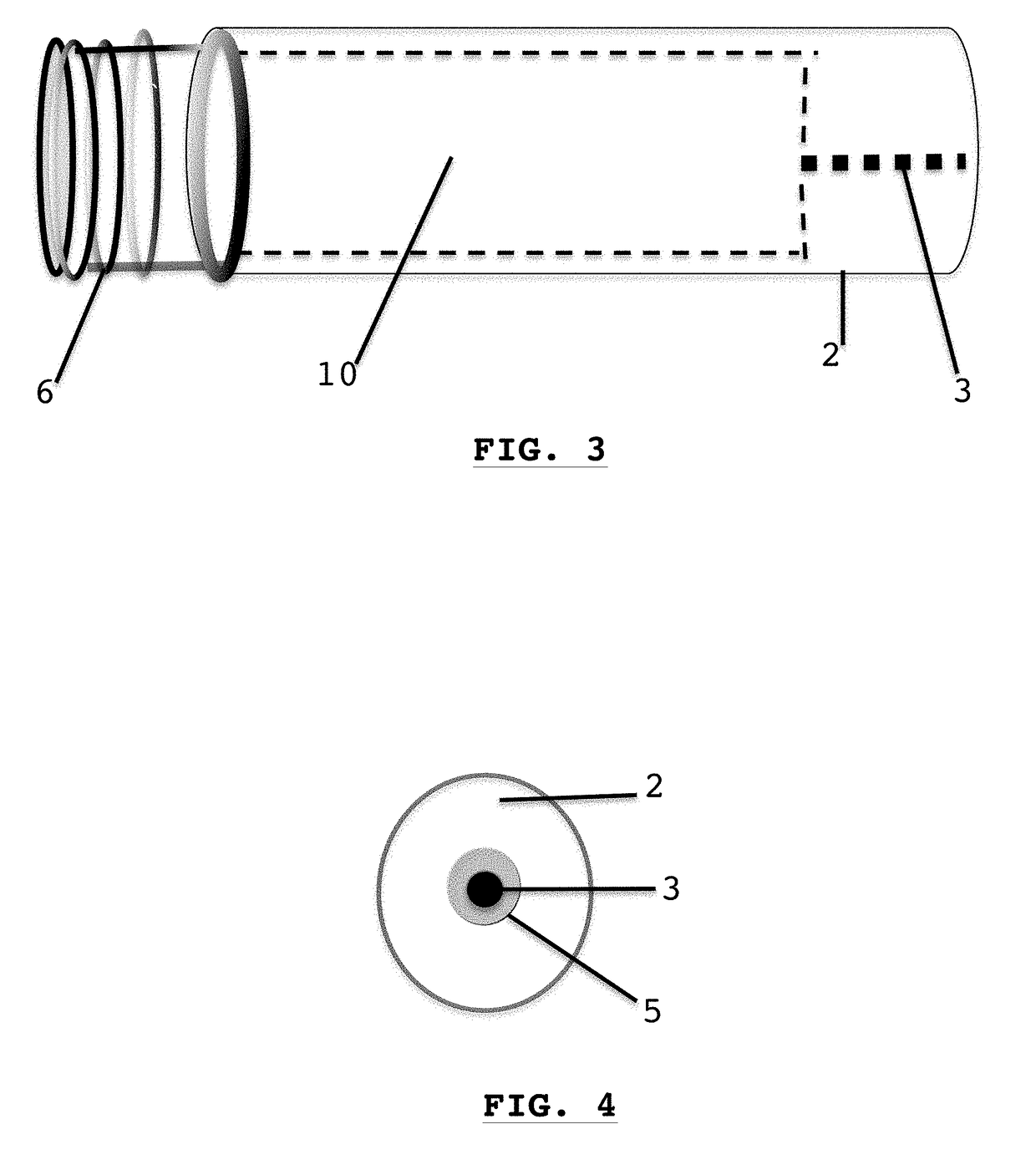
[0036]FIG. 3 depicts a partial cutaway of the top 2 showing the male threads 6 with the internal chamber 10. The threaded conduit 3 connects the chamber 10 to the atmosphere.

[0037]FIG. 4 shows the end opening of conduit 3 and the circular depressed area 5 at the end of the top 2.

[0038]FIG. 5 depicts the internal side view of the base 1 and the area of the reservoir 4. The female threads 7 of base 1 and the reservoir 4 are shown. A...


PUM


Abstract

A two-piece sterilizable vessel is sealed together containing devices and a solution that cleans and / or lubricates devices during heat sterilization. When placed inside a heat sterilizer, the vessel becomes pressurized and isolates the solution from the sterilizer's environment. This vessel has two parts: a base and a top.The base has an internal calibrated reservoir to measure the amount of solution within the vessel.The base's external dimensions, larger than the top, creates a lengthwise tilt of the vessel when placed on a flat surface. The top is positioned lower than the base. The purpose of the tilt is to allow the solution to flow from the reservoir to the vessel's top. This solution immerses the mechanics of the device.After sterilization is completed, the pressure relief valve in the vessel's top is activated to release the pressure within the vessel.

Description

CROSS REFERENCE TO RELATED APPLICATION[0001]This non-provisional application is a continuation-in-part of my co-pending provisional application titled, “Container for Autoclave” filed on Mar. 30, 2016 and given Ser. No. 62 / 390,454.BACKGROUND OF THE INVENTION[0002]Devices used in the medical and dental fields for procedures require cleaning, lubrication and sterilization. The heat sterilization process of a device affects the life span of the device. When the device is exposed to body fluids or sources of contaminates, the device requires cleaning and possibly lubrication of the device prior to sterilization. A device with moving parts (internal or external) are cleaned and lubricated prior to sterilization.[0003]When a device is not cleaned properly, contaminates remaining on the device will create a build up of sterilized layers of contaminates. This build up of contaminates may affect the function, sterilization efficiency and the life span of the device. The lubrication and clean...

Claims


Application Information

Patent Timeline
IPC IPC(8): B08B9/027A61L2/04F16N19/00A61L2/26
CPCB08B9/027A61L2/26A61L2202/14F16N19/00A61L2202/24A61L2/04A61L2/07A61L2202/182
Inventor OVERMYER, THAD J.OVERMYER, MICHAEL
Owner OVERMYER THAD J
Why Eureka
Eureka Blog
Learn More