Contact tip, gas diffuser, and nozzle for welding torch

a technology of welding torch and contact tip, which is applied in the direction of shielding support devices, electrode accessories, manufacturing tools, etc., can solve the problems of consumable replacement, undesirable activity, and wear of certain components of mig welding torch over time, so as to simplify the replacement and maximize the performance of these wear parts.

Pending Publication Date: 2017-10-05
ILLINOIS TOOL WORKS INC
View PDF7 Cites 9 Cited by
  • Summary
  • Abstract
  • Description
  • Claims
  • Application Information

AI Technical Summary

Benefits of technology

[0004]Therefore, it may be advantageous to provide a consumable design that maximizes the performance of these wear parts and simplifies their replacement. The pres

Problems solved by technology

In either style of MIG welding, certain components of the MIG welding torch tend to wear over time, and need replacement.
Consumable replacement is an

Method used


Image

  • Contact tip, gas diffuser, and nozzle for welding torch
  • Contact tip, gas diffuser, and nozzle for welding torch
  • Contact tip, gas diffuser, and nozzle for welding torch

Examples


Embodiment Construction

[0031]One or more embodiments of the present disclosure will be described below. In an effort to provide a concise description of these embodiments, all features of an actual implementation may not be described in the specification. It should be appreciated that in the development of any such actual implementation, as in any engineering or design project, numerous implementation-specific decisions are made to achieve the developers' specific goals, such as compliance with system-related and business-related constraints, which may vary from one implementation to another. Moreover, it should be appreciated that such a development effort might be complex and time consuming, but would nevertheless be a routine undertaking of design, fabrication, and manufacture for those of ordinary skill having the benefit of this disclosure.

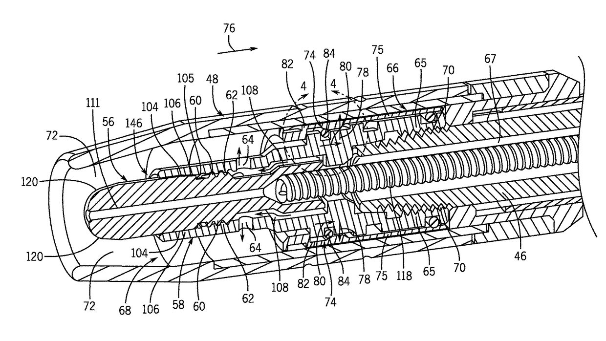
[0032]In conventional MIG welding systems, gas nozzles are axially pushed onto a gas diffuser, and the gas nozzle is held in place by a frictional fit between the ...


PUM

PropertyMeasurementUnit
Fractionaaaaaaaaaa
Fractionaaaaaaaaaa
Fractionaaaaaaaaaa

Abstract

In certain embodiments, a welding contact tip includes a first axial end portion having a welding wire outlet of an internal bore of the welding contact tip. The welding contact tip also includes a threaded middle portion adjacent the first axial end portion. The threaded middle portion includes external threads configured to mate with internal threads of a gas diffuser of a welding torch. The first axial end portion includes a tapered outer surface adjacent the threaded middle portion. In other embodiments, a welding torch assembly includes a gas diffuser having an outer circumferential groove having an outer surface with first and second walls that extend radially outward from first and second opposite axial sides of the outer surface, a nozzle having an inner circumferential rib with a tapered inner surface, and a compressible member disposed within the outer circumferential groove of the gas diffuser and the inner circumferential rib of the nozzle.

Description

CROSS REFERENCE TO RELATED APPLICATIONS[0001]This application is a Continuation-in-Part of U.S. patent application Ser. No. 15 / 370,884, entitled “Contact Tip and Liner Assembly for Welding Torch”, filed Dec. 6, 2016, which is a Non-provisional U.S. patent application of U.S. Provisional Patent Application No. 62 / 266,389, entitled “Contact Tip Having a Cooling Tail”, filed Dec. 11, 2015, and of U.S. Provisional Patent Application No. 62 / 368,478, entitled “Contact Tip and Liner Assembly for Welding Torch”, filed Jul. 29, 2016, all of which are incorporated herein by reference in their entireties for all purposes.BACKGROUND[0002]The present disclosure relates generally to MIG welding systems and, more particularly, to gas nozzles, gas diffusers, contact tips and liner assemblies for use in welding torches of MIG welding systems.[0003]MIG welding is a process that has increasingly become ubiquitous in various industries and applications. Manual MIG welding processes (i.e., welding in wh...

Claims


Application Information

Patent Timeline
IPC IPC(8): B23K9/16B23K9/29B23K9/26B23K9/173B23K9/28
CPCB23K9/164B23K9/173B23K9/293B23K9/26B23K9/285B23K9/295
Inventor CENTNER, ROBERT JOSEPH
Owner ILLINOIS TOOL WORKS INC
Why Eureka
Try Eureka