Vehicle fluid handling systems

Active Publication Date: 2017-10-05
AGILITY FUEL SYST LLC
View PDF1 Cites 14 Cited by
  • Summary
  • Abstract
  • Description
  • Claims
  • Application Information

AI Technical Summary

Benefits of technology

[0006]While conventional vehicle design is able to accommodate mounting fluid vessel of a plurality of fluid handling systems in different locations on the vehicle it would be advantageous to provide for greater integration of at least some components of more than one fluid handling system. There is a need to provide a fluid handling...

Problems solved by technology

This requires the natural gas fuel system to be positioned in on...

Method used


Image

  • Vehicle fluid handling systems
  • Vehicle fluid handling systems
  • Vehicle fluid handling systems

Examples


Embodiment Construction

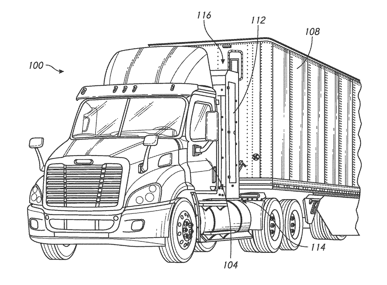
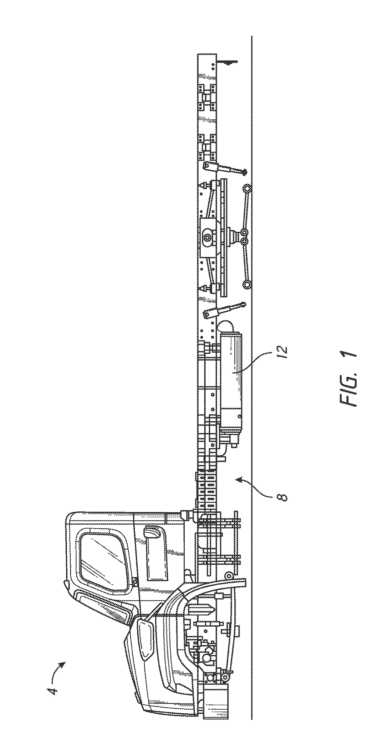
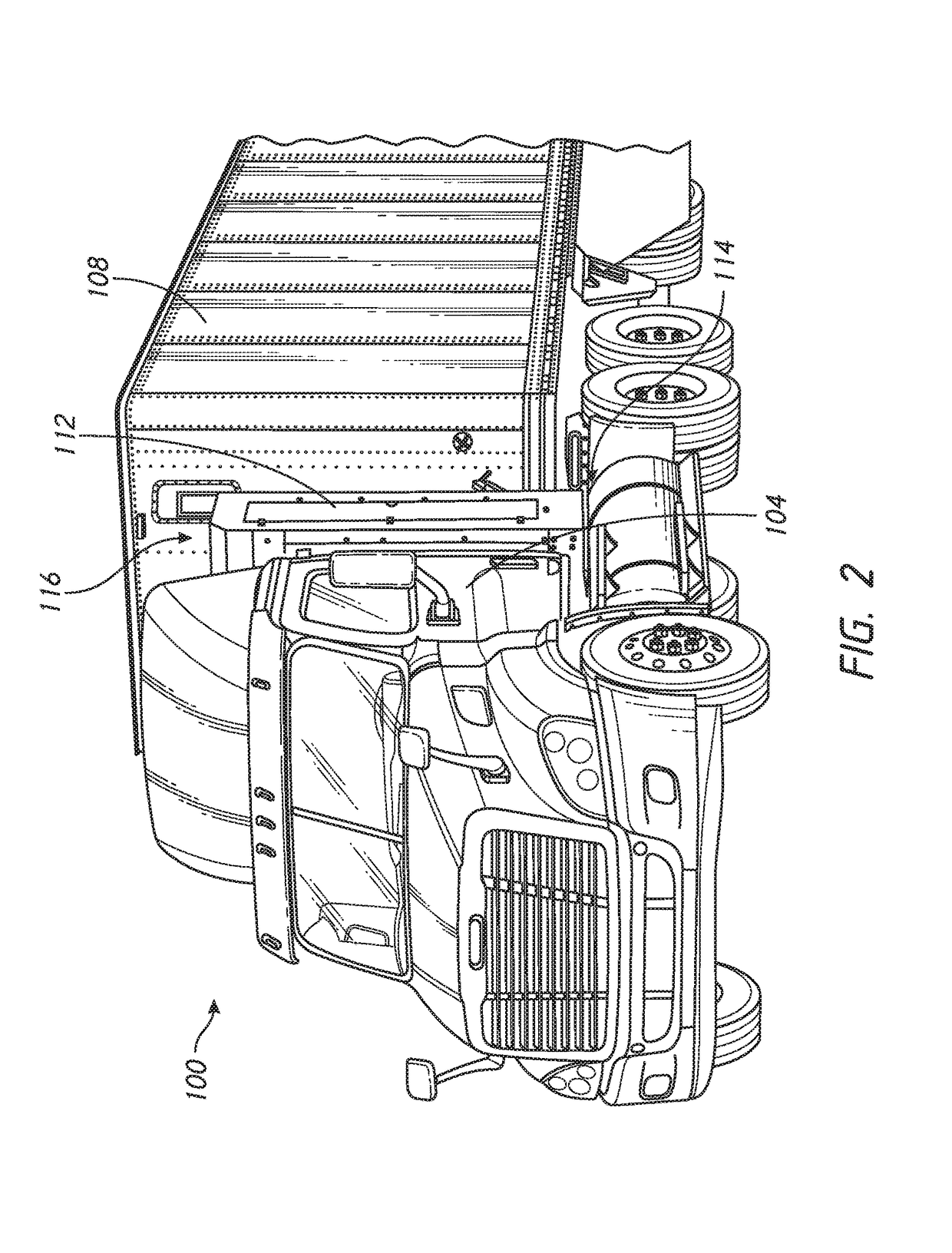
[0030]This application relates to advanced fluid storage and / or handling systems. Such systems can incorporate a plurality of fluid vessels, at least one of which is able to be subject to high pressure, to be provided working fluids to vehicle systems. The systems can combine a fuel pressure vessel for fuel storage and delivery of fuel to a vehicle engine with auxiliary fluid storage and delivery to auxiliary systems of the vehicle. The auxiliary fluid can be gas state fluid, such as air, useful in a pneumatic system, such as a brake system, an air horn, or other air powered system. The auxiliary fluid can be a liquid state fluid for use in operating a heavy duty door, a lift system, a compactor or another type of hydraulic system. The fluid system can be deployed in any location of a vehicle, such as behind the cab (see, e.g., FIG. 2), mounted to the roof-top (see, e.g., FIG. 10), mounted to the tail-gate (see, e.g., FIG. 12); and / or mounted to a side of a vehicle (see, e.g., FIG. ...


PUM


Abstract

A fluid system for a vehicle is provided. The fluid system is configured to couple to a chassis of the vehicle. A frame assembly of the fluid system is configured to couple with the chassis directly or with another component that is coupled, directly or indirectly, with the chassis. A cowling of the fluid system can enclose a fuel pressure vessel and an auxiliary fluid vessel. The auxiliary fluid vessel is configured to be placed in fluid communication with the component powered or operated by the fluid therein.

Description

INCORPORATION BY REFERENCE TO ANY PRIORITY APPLICATIONS[0001]This application claims priority to U.S. Provisional Application No. 62 / 317,280, filed on Apr. 1, 2016. The entire contents of the application identified above are incorporated by reference herein and made part of this specification.BACKGROUND OF THE INVENTIONField of the Invention[0002]This application is directed to novel fluid storage systems and to components thereof and to vehicles that incorporate such systems.Description of the Related Art[0003]Heavy duty vehicles form a critical part of transportation systems and economies of countries around the world. These vehicles perform a wide range of functions, from long haul and local delivery goods, to local route trash collection, to transporting passengers over long and short distances. These vehicles have many conventional vehicle systems. For instance, a fuel system provides fuel to a combustion engine that powers a drive train to move the vehicle. A braking system ap...

Claims


Application Information

Patent Timeline
IPC IPC(8): B60K15/07B60K15/01F17C13/08B60K15/03
CPCB60K15/07F17C2270/0563B60K15/01F17C13/084B60K2015/0636B60K2015/03157B60K2015/03256B60K2015/0321F17C2201/0109F17C2201/035F17C2201/056F17C2205/0107F17C2205/013F17C2205/0332F17C2205/0335F17C2205/0338F17C2221/033F17C2265/066F17C2270/0171F17C2270/0184F17C2270/0554B60K15/03006B60K15/063B60K2015/03315B60T17/06B60Y2200/145F17C2205/0111F17C2205/0176F17C2221/031F17C2221/035F17C2223/0115F17C2223/0153F17C2223/035F17C2223/036B60K15/04B60K2015/03118B60K2015/03243B60K2015/03309B60K2015/0639B60Y2200/144B65F3/14F17C13/08F17C13/083
Inventor SLOAN, TODD F.FORSBERG, CHRISLEDUC, JOSEPH ANTHONYHALTER, TOBIAH R.
Owner AGILITY FUEL SYST LLC
Why Eureka
Try Eureka