Supply of air to an air-conditioning circuit of an aircraft cabin

a technology for air conditioning circuits and aircraft, which is applied in the direction of machines/engines, energy-saving board measures, and efficient propulsion technologies, etc. it can solve the problems of overconsumption of fuel at idle power, noise, and significant oversupply of air supplied to aircraft, and achieve significant and uncontrolled fuel consumption and limit the effect of bleed air flow

Active Publication Date: 2017-10-05
SN DETUDE & DE CONSTR DE MOTEURS DAVIATION S N E C M A
View PDF3 Cites 19 Cited by
  • Summary
  • Abstract
  • Description
  • Claims
  • Application Information

AI Technical Summary

Benefits of technology

[0020]A first advantage of the invention is that the air-conditioning circuit can be supplied with air when the low-pressure body is not rotating or is hardly rotating, for example in the off mode. The electric motor then simply needs to be controlled such that the rotation speed of its output shaft imposes a rotation speed on the load compressor rotor depending on the desired air flow for supplying the circuit.
[0021]A further advantage of the invention is the possibility of controlling this air flow. Indeed, the air flow demand is not in line with the progression of the engine speed. The load compressor is generally dimensioned for a particular operating point, which means that it is mainly oversized for most of the other operating points. The result is mechanical take-off by the load compressor which is greater than the actual demand and which results in significant and uncontrolled fuel consumption.
[0022]The invention further makes it possible to not oversize the compressor in order to limit the bleed air flow to the demand only, and to not have to discharge the bleed air in the event of excessive air flow. This is particularly advantageous as this allows the discharge valves of the prior art to be dispensed with, which valves are heavy and bulky, and thus prevents the release of hot air discharged into the nacelle of the turboprop engine.
[0023]These advantages are facilitated by the fact that the rotation speed of the load compressor rotor is controlled by the motor. The compressor rotor is driven by the mechanical differential having two inputs respectively connected to the first and second shafts (of the electric motor and of the gearbox) and one output connected to the compressor rotor.
[0030]the control means comprise a further electric motor forming a redundancy.
[0032]rotating said first shaft in a direction opposite that of said second shaft, such that the rotation speed of said rotor (61) is less than that of said second shaft, during at least one operating phase of the turboprop engine, such as upon aircraft take-off.

Problems solved by technology

However, this has disadvantages, the most significant of which are as follows:the pressure of the air supplied to the aircraft significantly exceeds the demand, particularly during the aircraft climbing phase, which requires protection devices in the event of overpressure and the air ducts being dimensioned accordingly;the bleed air temperature in the region of the compressor significantly exceeds the regulatory requirement (maximum temperature upon passage into the fuel zones), which requires a cooling device (generally referred to as precooler), which is difficult to integrate in the nacelle, before sending the air into the circuit of the aircraft;considerable energy is lost, which penalises the consumption and the efficiency of the turboprop engine;the pressure in the compressor drops at idle power, which requires either raising the idle power level of the turboprop engine in order to have enough pressure in the circuit or bleeding air from two points on the compressor, which requires two bleed ports and as many valves to switch air bleeding from one port to the other, which is relatively complex.
In both cases, this leads to an overconsumption of fuel at idle power;when the bleed air flow is excessive, which occurs in certain turboprop engine operating phases, bleed air is discharged, i.e. it is generally expelled and released in the nacelle of the turboprop engine in order to reduce the flow of bleed air, which is particularly noisy.
However, the operation of this engine is optimised on the ground and therefore is not efficient at altitude.
Its use, with the exception of an engine malfunction, involves additional fuel consumption compared to the preceding technique.
Furthermore, not all aircraft are equipped with an engine of the APU type.
However, this solution is unsatisfactory as the rotation speed of the high-pressure body varies excessively depending on the operating conditions such that the rotation speed of the rotor of the dedicated compressor will be too low at idle power for this compressor to be able to supply an air flow to the conditioning circuit at the minimum required pressure.
However, this solution is also unsatisfactory as it involves a loss of efficiency due to the conversion of mechanical energy into electric energy by the electric generator intended to be driven by the PGB or the AGB and to supply the electric motor with power, and due to the conversion of electric energy into mechanical energy by the dedicated compressor.
The speed of the propeller can be within a fairly limited range as it can no longer be operational if it slows down excessively.

Method used


Image

  • Supply of air to an air-conditioning circuit of an aircraft cabin
  • Supply of air to an air-conditioning circuit of an aircraft cabin
  • Supply of air to an air-conditioning circuit of an aircraft cabin

Examples


Embodiment Construction

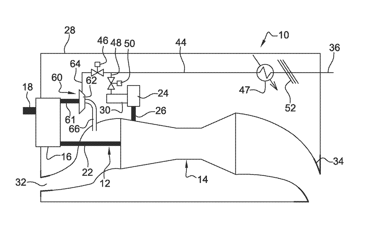
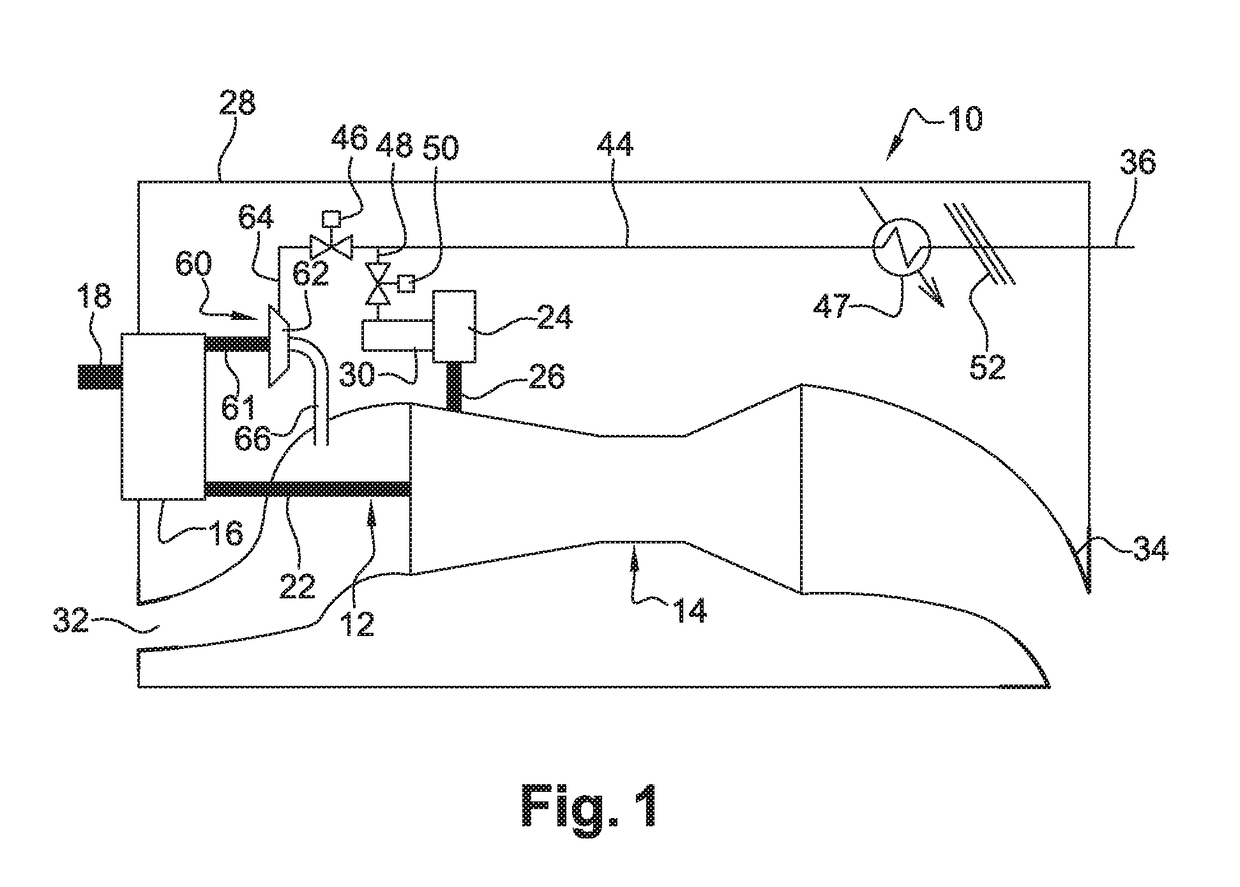
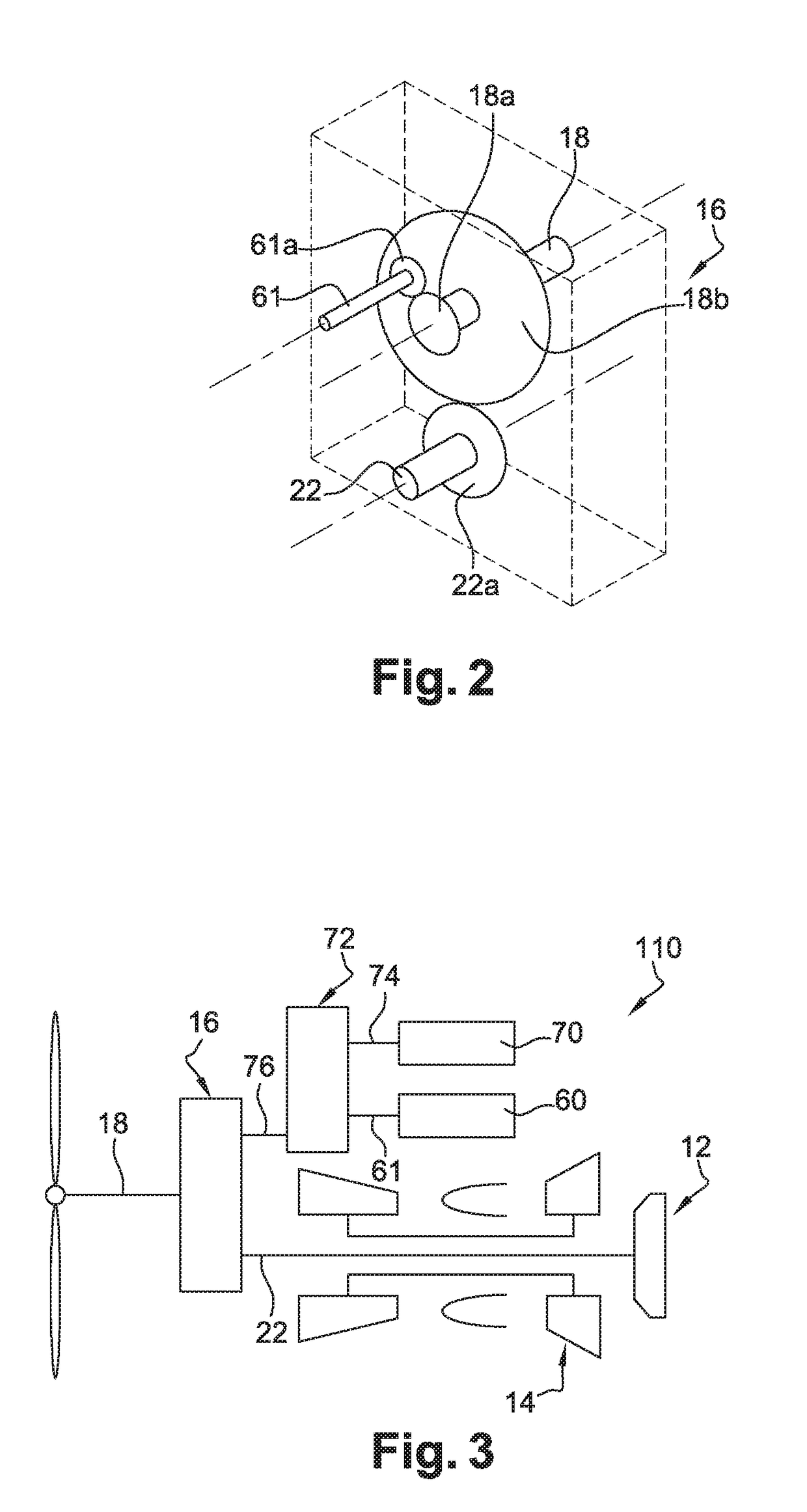
[0043]FIG. 1 shows an aircraft turboprop engine 10, which herein is of the twin-spool type and comprises a low-pressure body 12 and a high-pressure body 14. The low-pressure body 12 drives a thrust propeller by means of a gearbox 16 or reduction gearbox, commonly referred to as PGB (Power Gear Box). Only the shaft 18 of the thrust propeller is shown in FIG. 1.

[0044]The low-pressure body 12 herein comprises only a turbine rotor connected by a shaft to the gearbox 16. The high-pressure body 14 comprises a compressor rotor connected by a shaft to a turbine rotor. The shaft of the high-pressure body 14, referred to as HP shaft, is tubular, and the shaft of the low-pressure body 12, referred to as LP shaft or power shaft, passes coaxially through said HP shaft. The LP shaft comprises a gear (not shown) at one end that is coupled to the shaft 18 of the thrust propeller by means of a series of gears of the gearbox 16.

[0045]The turboprop engine 10 comprises a gearbox 24 (referred to as AGB ...


PUM


Abstract

Aircraft turboprop engine (110), comprising at least one low-pressure body (12) and one high-pressure body (14), the low-pressure body driving a thrust propeller by means of a gearbox (16), the turboprop engine further comprising means for supplying air to an air-conditioning circuit (36) of an aircraft cabin, said supply means comprising a load compressor (60), a rotor (61) of which is coupled to said low-pressure body by means of said gearbox, characterised in that said supply means further comprise means for controlling the rotation speed of the rotor (61) of said compressor (60), which means comprise an electric motor (70), and a mechanical differential (72) for coupling a first output shaft (74) of said electric motor to a second output shaft (76) of said gearbox and to said compressor rotor (61), such that the rotation speed (V3) of said rotor depends on the respective rotation speeds (V1, V2) of said first and second output shafts.

Description

TECHNICAL FIELD[0001]The present invention relates to the supply of air to an air-conditioning circuit of a cabin of an aircraft that is equipped with at least one turboprop engine.PRIOR ART[0002]On board an aircraft, air needs to be available in order to be able to perform certain functions, such as air-conditioning in the pilot cabin and the passenger cabin or de-icing of certain aircraft components. At high altitudes, oxygen rarefies and the air pressure drops. This means that the aircraft cabins need to be pressurised in order to ensure the comfort and the survival of the passengers during a flight. To this end, air having a minimum pressure level (generally between 0.8 and 1 bar) and a controlled temperature (regulatory requirement) must be supplied to the air-conditioning circuit. Therefore, an aircraft is equipped with an air-conditioning circuit that is supplied by the one or more engines of the aircraft, which are turboprop engines within the scope of the invention.[0003]Ty...

Claims


Application Information

Patent Timeline
Patent Type & Authority Applications(United States)
IPC IPC(8): F04D27/00B64D27/10F02C6/20B64D13/06F02C7/36F04D25/06F04D25/02B64D13/02F02C7/32
CPCF04D27/004B64D13/02B64D27/10F02C6/206B64D2013/0644F02C7/36F04D25/06F04D25/028B64D13/06F02C7/32F05D2260/40311Y02T50/50Y02T50/60
Inventor RICORDEAU, JULIEN ALEXIS LOUISMISSOUT, MARC
Owner SN DETUDE & DE CONSTR DE MOTEURS DAVIATION S N E C M A
Why Eureka
Try Eureka