Filtering device for dust and other pollutants

a filter device and dust filter technology, applied in the direction of dispersed particle separation, human health protection, separation processes, etc., can solve the problems of high maintenance costs, frequent periodic maintenance, system drawbacks, etc., and achieve low construction and management costs, the effect of efficient purification of fumes

Active Publication Date: 2017-10-12
RIZZO ROCCO
View PDF1 Cites 3 Cited by
  • Summary
  • Abstract
  • Description
  • Claims
  • Application Information

AI Technical Summary

Benefits of technology

[0011]The object of the present invention is to overcome the drawbacks described above and in particular to provide

Problems solved by technology

These systems, however, have a series of drawbacks.
For example, they require frequent periodic maintenance and therefore have high maintenance costs.
Moreover, they are subject to malfunctions due to the significant pressure losses.
If the diameter of the holes were too small, there would be problems with the air flow.
Therefore, these filters are not suitable for retaining in an efficient manner ultrafine dust particles, with a diameter of less than 5 microns.
Many of these systems are also not compatible with high temperatures, are adversely affected by the presence of moisture (bag filters) and sometimes have a very limited efficiency as regards filtering of particulate matter (

Method used


Image

  • Filtering device for dust and other pollutants
  • Filtering device for dust and other pollutants
  • Filtering device for dust and other pollutants

Examples


Embodiment Construction

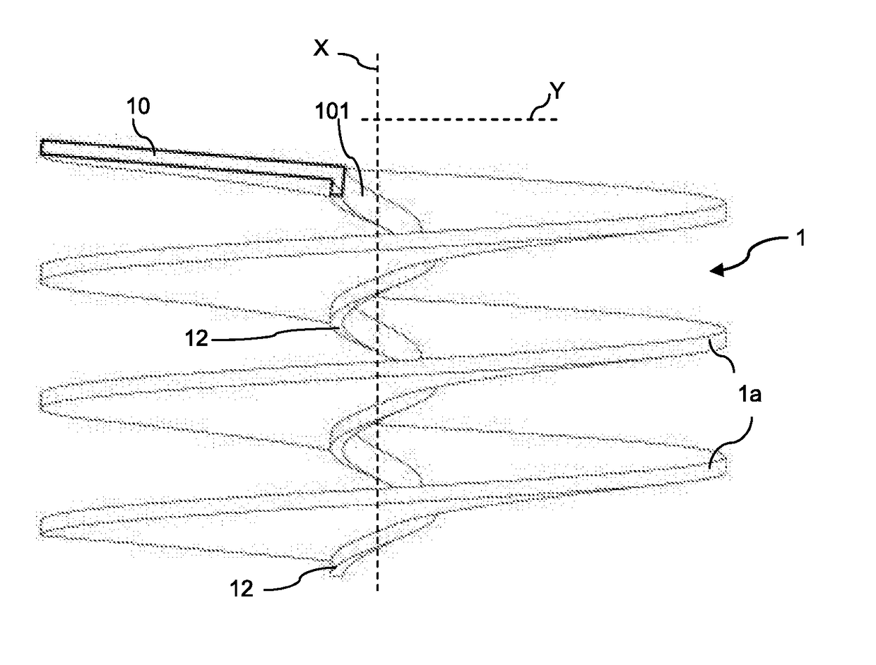
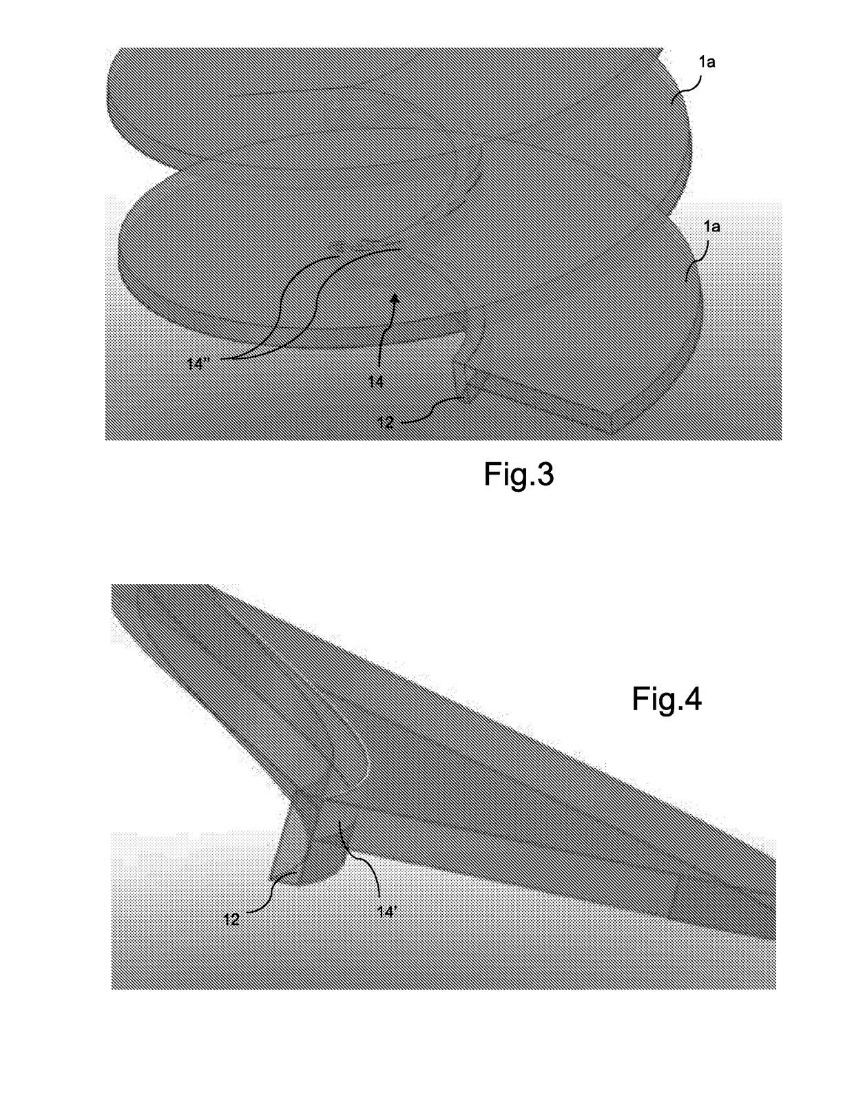
[0023]With reference to the aforementioned figures, the device comprises a substantially spiral duct 1 which extends spirally around a vertical axis or generatrix X in the form of superimposed volutes 1a. The generatrix also defines the direction of advancing movement of the fumes from an inlet mouth (not shown) to an outlet mouth 10 of said spiral.

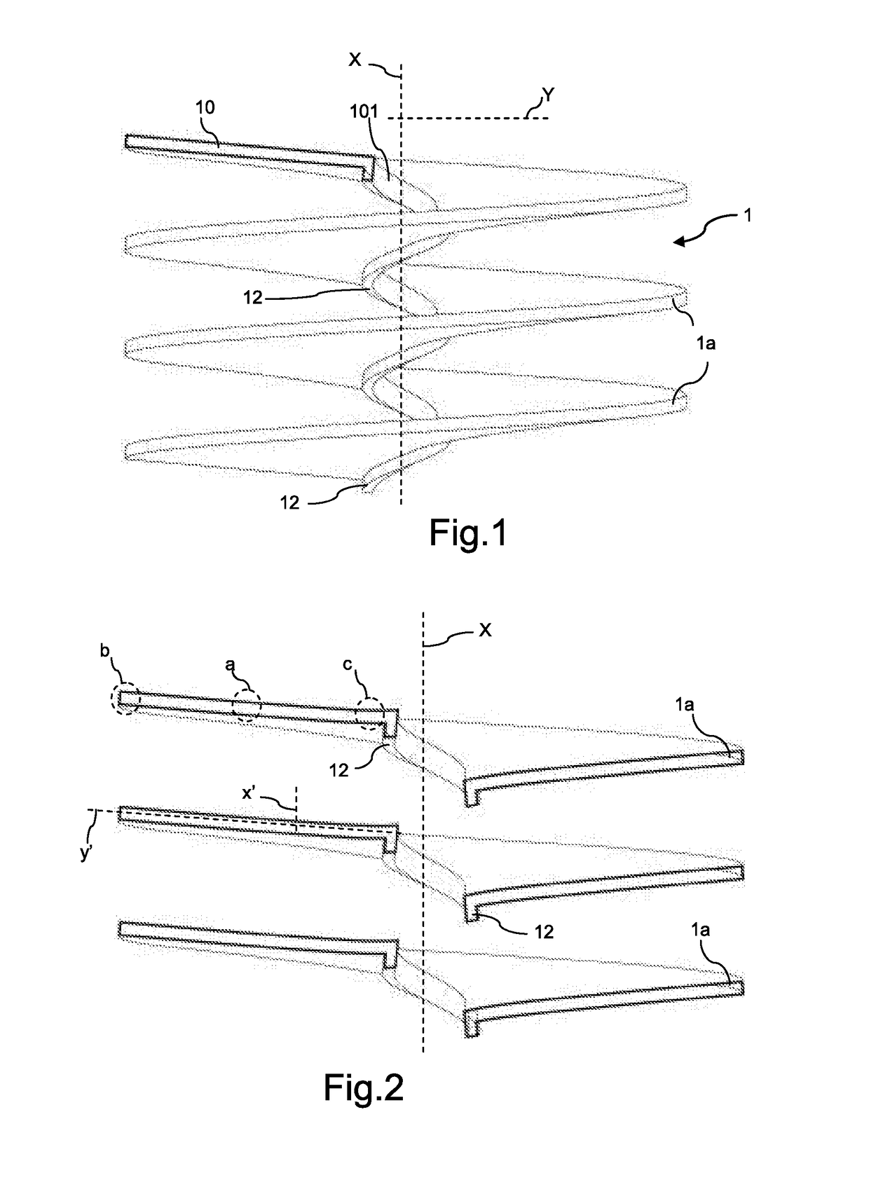
[0024]In even greater detail and with reference in particular to FIG. 2, the inlet mouth and the outlet mouth are arranged in an operational continuous manner in relation to the spiral.

[0025]The filter is arranged vertically, namely the inlet mouth and outlet mouth are arranged mutually superimposed along the generatrix. Optionally, the outlet mouth and the inlet mouth may be inverted, namely the flow of the fumes may travel equally well along the spiral upwards (in this case the inlet mouth is arranged at a height lower than that of the outlet mouth) or downwards (in this case the inlet mouth is at greater height than the outlet mouth).

[...


PUM

PropertyMeasurementUnit
Pressureaaaaaaaaaa
Angleaaaaaaaaaa
Angleaaaaaaaaaa

Abstract

The present invention relates to the filtering of fumes emitted by industrial processes such as those used in iron and steel works, refineries, waste-to-energy plants and the like and in particular relates to a filtering device for fine and ultrafine dust particles and other polluting agents.

Description

TECHNICAL FIELD OF THE INVENTION[0001]The present invention relates to the sector dealing with the filtering of fumes emitted by industrial processes (such as those used in iron and steel works, refineries, waste-to-energy plants and the like) and in particular relates to a filtering device for fine and ultrafine dust particles and other polluting agents.BACKGROUND OF THE INVENTION[0002]As is known, the working processes commonly used in industrial plants such as iron and steel works, refineries, waste-to-energy plants and the like produce fumes which contain toxic, pathogenic and / or polluting agents such as particulate matter, dioxins, furans, polychlorobiphenyls, chlorophenoxy compounds, nitrogen oxides or dioxides, sulphur dioxide, etc.[0003]In general, particulate matter, anhydrides and nitrogen monoxides and dioxides are irritants for the respiratory systems, causing in human beings respiratory illnesses and diseases such as asthma, bronchitis and infections of the respiratory ...

Claims


Application Information

Patent Timeline
IPC IPC(8): B01D53/34B01D53/70B01D45/16B01D53/56B01D53/79B01D53/50
CPCB01D53/34B01D53/79B01D53/50B01D47/10B01D53/56B01D53/70B01D47/06B01D45/16Y02A50/2351
Inventor DI NOI, ANGELO
Owner RIZZO ROCCO
Why Eureka
Try Eureka