Control system for internal combustion engine

a control system and internal combustion engine technology, applied in the direction of electric control, machines/engines, output power, etc., can solve the problems of achieve the effect of suppressing the deterioration of combustion nois

Inactive Publication Date: 2017-10-12
TOYOTA JIDOSHA KK
View PDF0 Cites 27 Cited by
  • Summary
  • Abstract
  • Description
  • Claims
  • Application Information

AI Technical Summary

Benefits of technology

[0005]The present disclosure was made with such a problem in mind and includes embodiments that may suppress deterioration of the combustion noise when making the premixed gas burn by the compression-ignition combustion when the internal combustion engine is in a transition state.
[0007]According to this aspect of the present disclosure, it is possible to suppress the deterioration of the combustion noise when making the premixed gas burn by the compression-ignition combustion when in the transition state.

Problems solved by technology

For this reason, in the transition state, the fuel will not burn by the self-ignition combustion mode divided into two stages and the combustion noise is liable to deteriorate.

Method used


Image

  • Control system for internal combustion engine
  • Control system for internal combustion engine
  • Control system for internal combustion engine

Examples


first embodiment

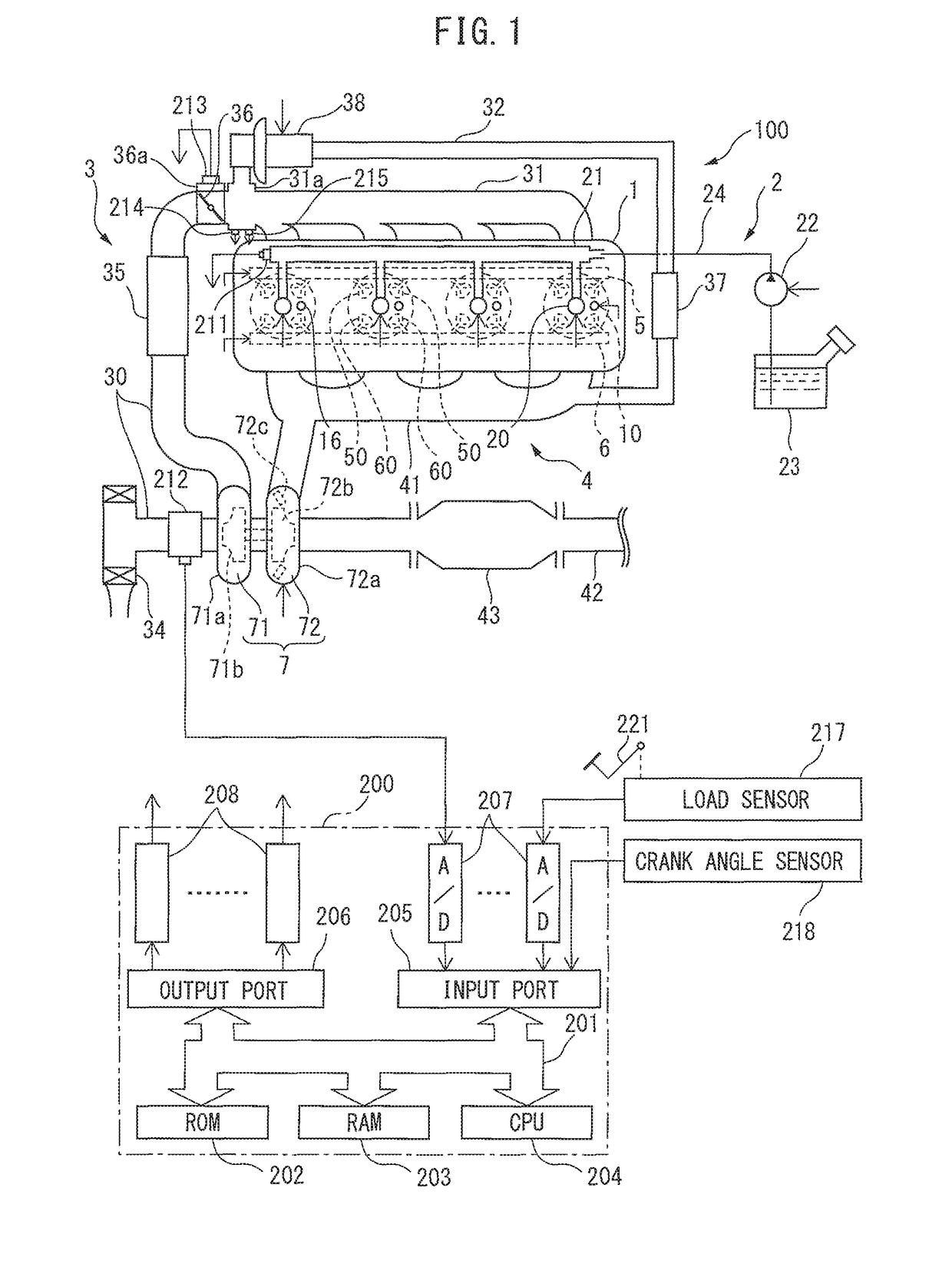
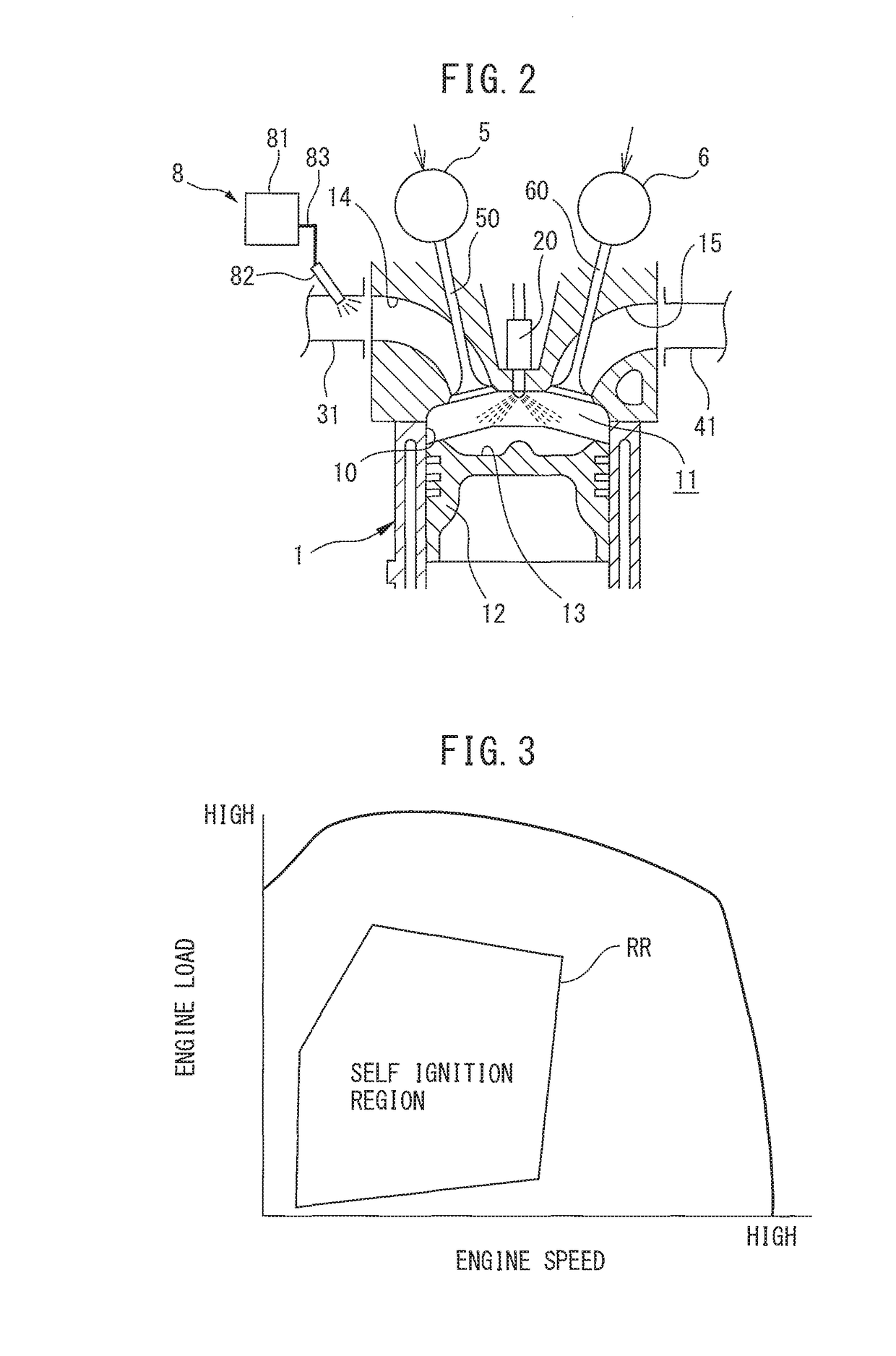
[0026]FIG. 1 is a schematic view of the constitution of an internal combustion engine 100 and an electronic control unit 200 controlling the internal combustion engine 100 according to a first embodiment of the present disclosure. FIG. 2 is a cross-sectional view of an engine body 1 of the internal combustion engine 100.

[0027]The internal combustion engine 100 is provided with an engine body 1 provided with a plurality of cylinders 10, a fuel supply system 2, an intake system 3, an exhaust system 4, an intake valve operating system 5, an exhaust valve operating system 6, and an ozone supply system. 8 (see FIG. 2).

[0028]The engine body 1 burns fuel in combustion chambers 11 formed at the cylinders 10 (see FIG. 2) to for example generate drive force for driving a vehicle etc. The engine body 1 is provided with one spark plug 16 for each cylinder facing the combustion chamber 11 of each cylinder 10. Further, the engine body I is provided with a pair of intake valves 50 and a pair of ex...

second embodiment

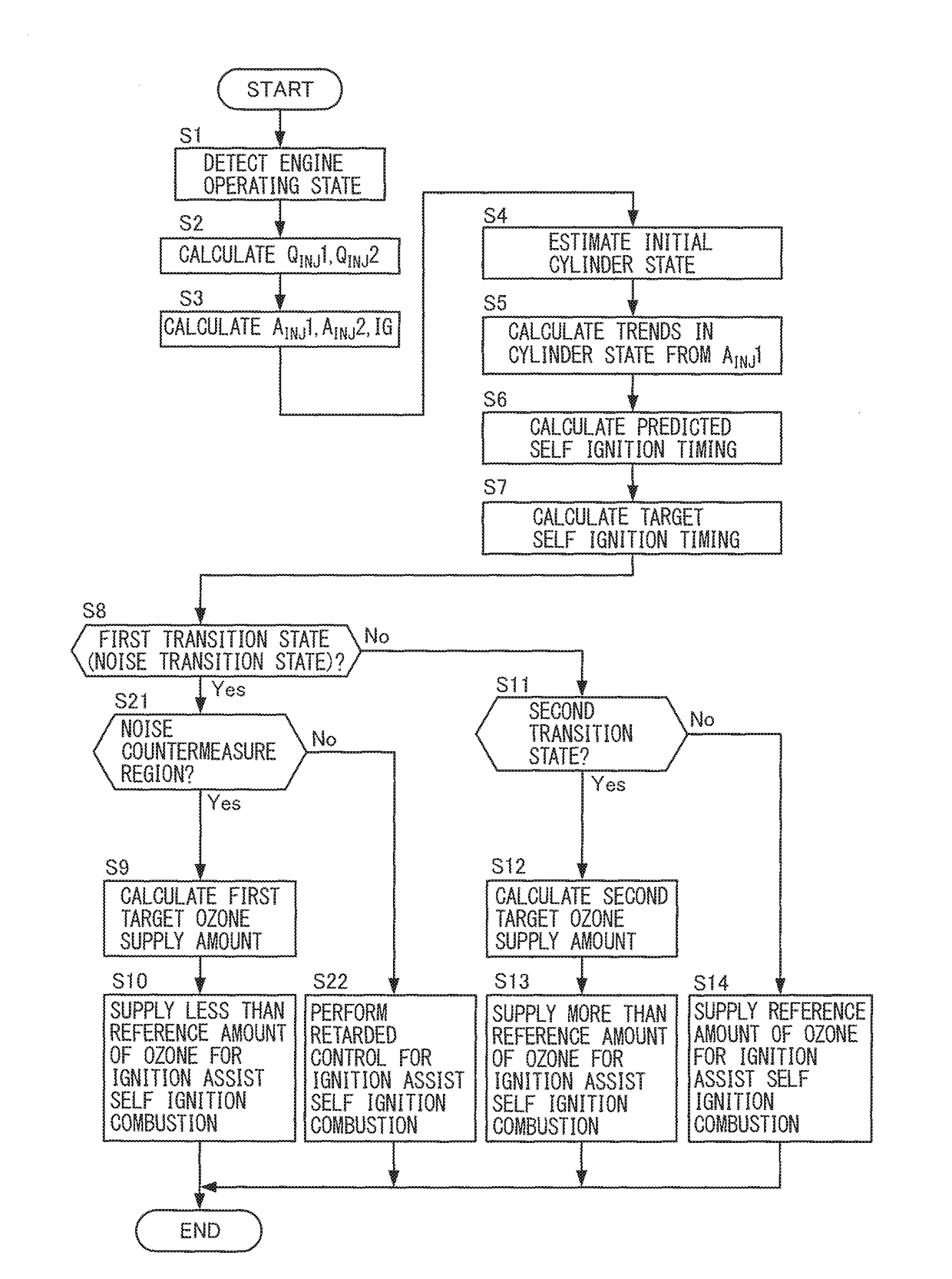
[0140]Next, a second embodiment will be explained. The present embodiment differs from the first embodiment on the point of controlling the amount of supply of ozone to suppress deterioration of the combustion noise when the engine load is a predetermined load or more in the self-ignition region RR. Below, this point of difference will be focused on for the explanation.

[0141]As explained above referring to FIG. 5, when making the premixed gas burn by the compression-ignition combustion, the combustion noise increases the greater the amount of fuel consumed by the compression -ignition combustion. For this reason, in the engine low load region where the total fuel injection amount QINJ1 is originally small, even if the state becomes the first transition state and the combustion noise increases, sometimes it falls within the allowable noise value. Therefore, in such an engine low load region, when the state becomes the first transition state, it is not necessarily required to reduce t...


PUM


Abstract

A control system for an internal combustion engine is provided with a combustion control part, an operating state judging part judging if an engine operating state is a steady state or a combustion noise is a noise transition state where the combustion noise increases over a predetermined allowable noise value when burning fuel by an ignition-assist self-ignition combustion, and an ozone supply control part controlling the amount of ozone supplied to the combustion chamber by the ozone supply system. The ozone supply control part controls the amount of supply of ozone to a predetermined reference amount when the state is judged to be the steady state and controls the amount of supply of ozone to an amount of supply smaller than the reference amount or makes the amount of supply of ozone zero when the state is judged to be the noise transition state.

Description

CROSS-REFERENCE TO RELATED APPLICATION[0001]This application claims priority based on Japanese Patent Application No. 2016-077482 filed with the Japan Patent Office on Apr. 7, 2016, the entire contents of which are incorporated into the present specification by reference.TECHNICAL FIELD[0002]The present disclosure relates to a control system for an internal combustion engine.BACKGROUND ART[0003]JP2014-025373A discloses a conventional control system for an internal combustion engine configured so as to perform first fuel injection when the concentration of the active species in a cylinder is a predetermined value or more, then perform second fuel injection when the concentration of active species has become less than the predetermined value to burn premixed gas by a compression-ignition combustion. According to 3P2014-025373A, it is possible to divide fuel injected into a cylinder into two stages to burn the fuel by the self-ignition combustion mode, so it is considered possible to r...

Claims


Application Information

Patent Timeline
Patent Type & Authority Applications(United States)
IPC IPC(8): F02D41/00F02D37/02F02B11/00F02D41/14F02D41/04F02D41/40
CPCF02D41/0025F02D41/04F02D41/40F02D2200/025F02D41/1497F02D37/02F02B11/00F02B1/12F02D13/0207F02D13/0273F02D19/12F02D35/024F02D35/026F02D35/028F02D41/0007F02D41/006F02D41/3041F02D41/3047F02D41/3064F02D2041/001F02D2041/1433F02D2041/389F02M25/10F02M26/01F02M26/05Y02T10/12
Inventor TSUDA, SATOSHI
Owner TOYOTA JIDOSHA KK
Why Eureka
Try Eureka