System and method for measuring velocity profiles

a velocity profile and velocity measurement technology, applied in the field of magnetic resonance imaging, can solve the problems of signal loss, velocity profile may not be accurate, and certain types of drilling mud flowing in a conduit or pipe can be measured, so as to reduce the echo time of a magnetic pulse

Active Publication Date: 2017-10-12
ASPECT IMAGING
View PDF0 Cites 0 Cited by
  • Summary
  • Abstract
  • Description
  • Claims
  • Application Information

AI Technical Summary

Benefits of technology

[0005]One advantage of the invention includes a reduction in an echo time of a magnetic pulse by encoding velocity information of a fluid affected by the pulse into a longitudinal magnetization of the pulse.
[0006]An additional advantage of the invention can be due to the fact that the velocity determination is entirely ‘model-free’, in the sense that it does not depend on any modeling of how relaxation (longitudinal or transverse) may affect the results, since the results can be independent on spin relaxation and depend only on the flow rate itself.
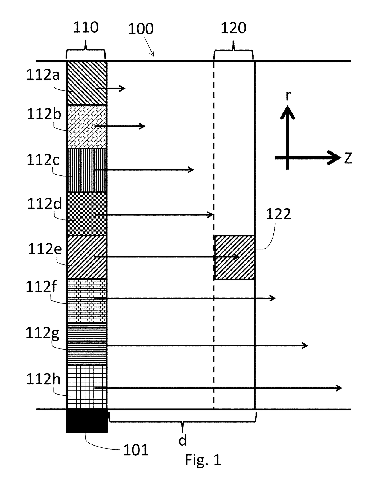
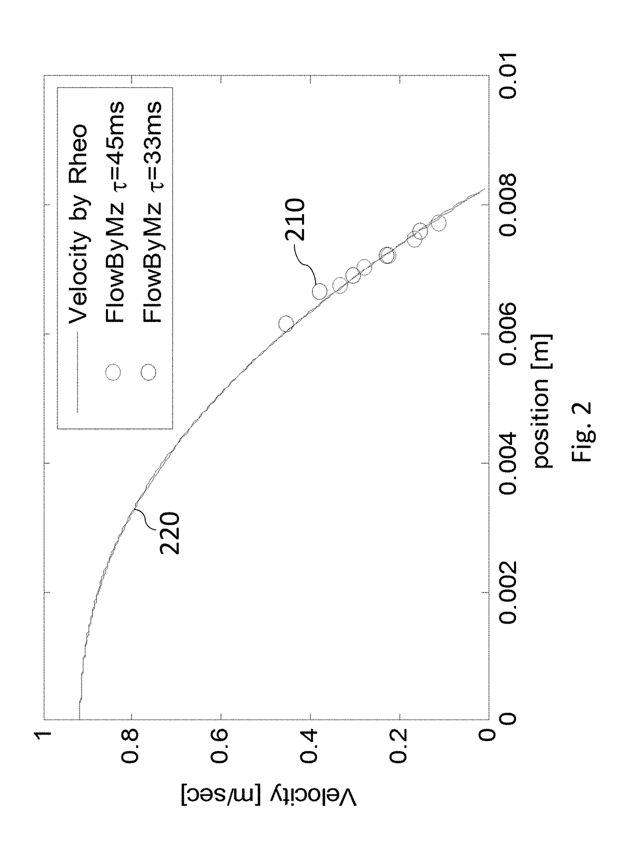
[0007]There is thus provided, in accordance with some embodiments of the invention, a method of determining a velocity profile of a fluid flowing through a conduit, the method including applying a saturation pulse on spins of magnetic field-sensitive nuclei in the fluid, measuring a signal of the fluid to determine position of the magnetic field-sensitive nuclei, the measurement carried out at a recovery time ‘TR’ and at a distance within the conduit, determining within the conduit a radial distance ‘r’ characterized by a local minimum in the measured signal, wherein the radial distance ‘r’ is measured from the center of the conduit, and determining a velocity profile of the fluid at the radial distance, based on the magnetic field-sensitive nuclei.
[0008]In some embodiments, the position of the local minimum in the signal corresponds to the local flow velocity. In some embodiments, applying a saturation pulse is carried out for a tagging slice of the fluid located at a predetermined position along said flow. In some embodiments, the measurement is carried out for a corresponding readout slice of the fluid, and wherein the readout slice is at a predetermined distance from the tagging slice.
[0009]In some embodiments, the method includes encoding the velocity in a direction parallel to the flow of the fluid within the conduit. In some embodiments, the method further includes encoding the velocity in a direction perpendicular to the flow of the fluid within the conduit, and comparing the measured velocity in both directions to determine the velocity profile. In some embodiments, the method includes measuring the intensity of the signal as a function of position.
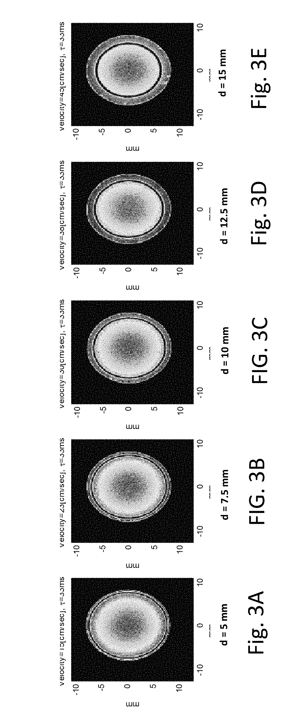
[0010]In some embodiments, the measurement is carried out for low flow regions near the wall of the conduit. In some embodiments, the method further includes varying the value of ‘d’, and determining a velocity profile v(r) as a function of radial distance ‘r’.

Problems solved by technology

In magnetic resonance imaging (MRI), some measurements of certain types of drilling mud flowing in a conduit or pipe can be lost, particularly as most of the signal that originates at the edges of the pipe corresponds to low velocity and high shear rate.
However, such measurements typically can have signal loss such that the velocity profile may not be accurate.
Thus, finding an accurate MRI method for measuring velocity profiles in drilling mud remains a long-felt yet unmet need.

Method used


Image

  • System and method for measuring velocity profiles
  • System and method for measuring velocity profiles
  • System and method for measuring velocity profiles

Examples


Embodiment Construction

[0019]Although embodiments of the invention are not limited in this regard, discussions utilizing terms such as, for example, “processing,”“computing,”“calculating,”“determining,”“establishing”, “analyzing”, “checking”, or the like, can refer to operation(s) and / or process(es) of a computer, a computing platform, a computing system, or other electronic computing device, that manipulates and / or transforms data represented as physical (e.g., electronic) quantities within the computer's registers and / or memories into other data similarly represented as physical quantities within the computer's registers and / or memories or other information non-transitory storage medium that can store instructions to perform operations and / or processes. Although embodiments of the invention are not limited in this regard, the terms “plurality” and “a plurality” as used herein can include, for example, “multiple” or “two or more” and can be used throughout the specification to describe two or more compon...


PUM

PropertyMeasurementUnit
flip angleaaaaaaaaaa
diameteraaaaaaaaaa
distancesaaaaaaaaaa

Abstract

Method of determining a velocity profile of a fluid flowing through a conduit, the method including applying a saturation pulse on spins of magnetic field-sensitive nuclei in the fluid, measuring a signal of the fluid to determine position of the magnetic field-sensitive nuclei, the measurement carried out at a recovery time ‘TR’ and at a distance ‘d’ within the conduit, determining within the conduit a radial distance ‘r’ characterized by a local minimum in the measured signal, wherein the radial distance ‘r’ is measured from the center of the conduit, and determining a velocity profile of the fluid at the radial distance, based on the magnetic field-sensitive nuclei.

Description

CROSS REFERENCE TO RELATED APPLICATIONS[0001]This application claims priority to and the benefit of Provisional Application No. 62 / 321,507, filed Apr. 12, 2016, the entire contents of which are incorporate herein by reference in their entireties.FIELD OF THE INVENTION[0002]Generally, the invention relates to measurements of velocity profiles in fluids. In particular, the invention relates to magnetic resonance imaging (MRI) methods for measuring velocity profiles in flows of drilling mud.BACKGROUND OF THE INVENTION[0003]In magnetic resonance imaging (MRI), some measurements of certain types of drilling mud flowing in a conduit or pipe can be lost, particularly as most of the signal that originates at the edges of the pipe corresponds to low velocity and high shear rate. Such signal loss can be evident even in simple spin-echo (SE) images, e.g. images that do not have any intentional velocity-encoding gradients. The degree of signal loss in such measurements can show a positive corre...

Claims


Application Information

Patent Timeline
Patent Type & Authority Applications(United States)
IPC IPC(8): G01F1/716G01N24/08
CPCG01N24/081G01F1/716G01R33/4838G01R33/56308
Inventor BENDEL, PETERSHAPIRA, BOAZ
Owner ASPECT IMAGING
Why Eureka
Try Eureka