Acoustic partition for removable panel finishing system

a technology of acoustic partition and finishing system, which is applied in the field of acoustic partition, can solve the problems that none of the existing acoustical products provide sufficient sound attenuation properties for use in homes and commercial buildings, and achieve the effect of reducing echo time and easy cutting

Inactive Publication Date: 2007-06-07
OWENS CORNING INTELLECTUAL CAPITAL LLC
View PDF40 Cites 23 Cited by
  • Summary
  • Abstract
  • Description
  • Claims
  • Application Information

AI Technical Summary

Benefits of technology

[0022] It is an advantage of the present invention that unlike conventional drywall walls, there is little or no dust generated during installation of the removable panel finishing system.
[0023] It is another advantage of the present invention that the acoustic membrane can be easily cut, such as to fit around doors and / or windows.
[0024] It is yet another advantage of the present invention that a removable panel finishing system utilizing the acoustic membrane absorbs approximately 75% of the sound energy within the room.
[0025] It is a further advantage of the present invention that the acoustic membrane reduces echo time to less than about one second.
[0026] It is also an advantage of the present invention that the acoustic membrane can be fabricated to have an aesthetically pleasing surface.
[0027] The foregoing and other objects, features, and advantages of the invention will appear more fully hereinafter from a consideration of the detailed description that follows. It is to be expressly understood, however, that the drawings are for illustrative purposes and are not to be construed as defining the limits of the invention.

Problems solved by technology

Despite the numerous acoustical insulation products in existence in the art, none of the existing acoustical products provide sufficient sound attenuating properties for use in homes and commercial buildings.

Method used


Image

  • Acoustic partition for removable panel finishing system
  • Acoustic partition for removable panel finishing system
  • Acoustic partition for removable panel finishing system

Examples


Embodiment Construction

[0039] Unless defined otherwise, all technical and scientific terms used herein have the same meaning as commonly understood by one of ordinary skill in the art to which the invention belongs. Although any methods and materials similar or equivalent to those described herein can be used in the practice or testing of the present invention, the preferred methods and materials are described herein. All references cited herein, including published or corresponding U.S. or foreign patent applications, issued U.S. or foreign patents, or any other references, are each incorporated by reference in their entireties, including all data, tables, figures, and text presented in the cited references.

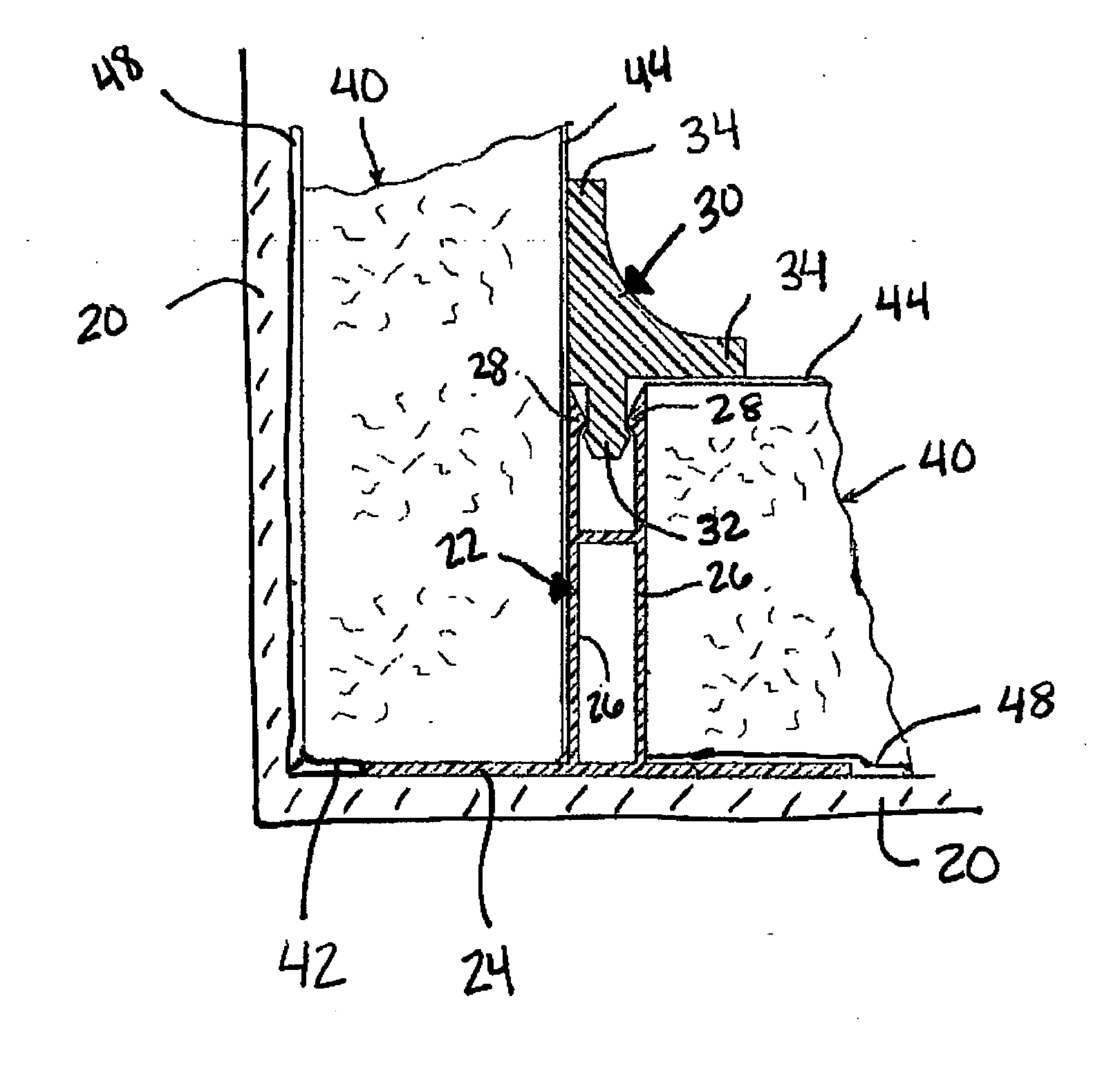
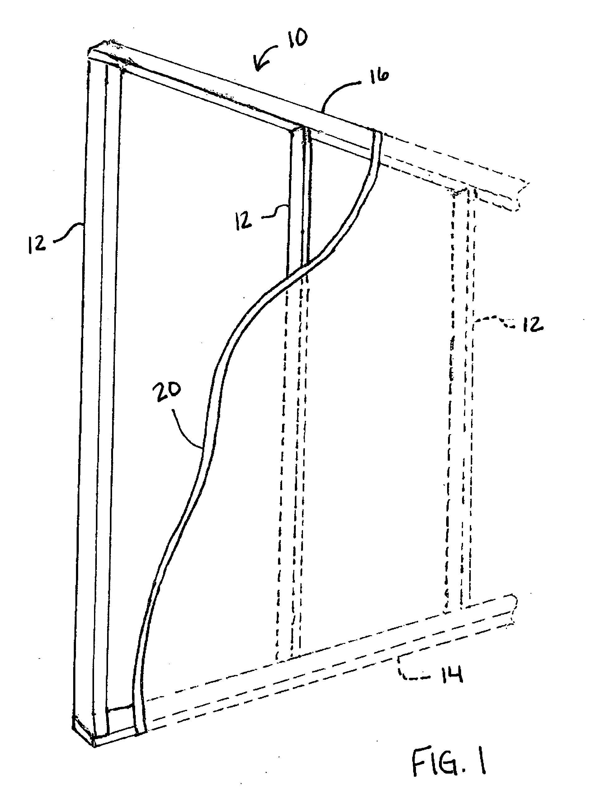
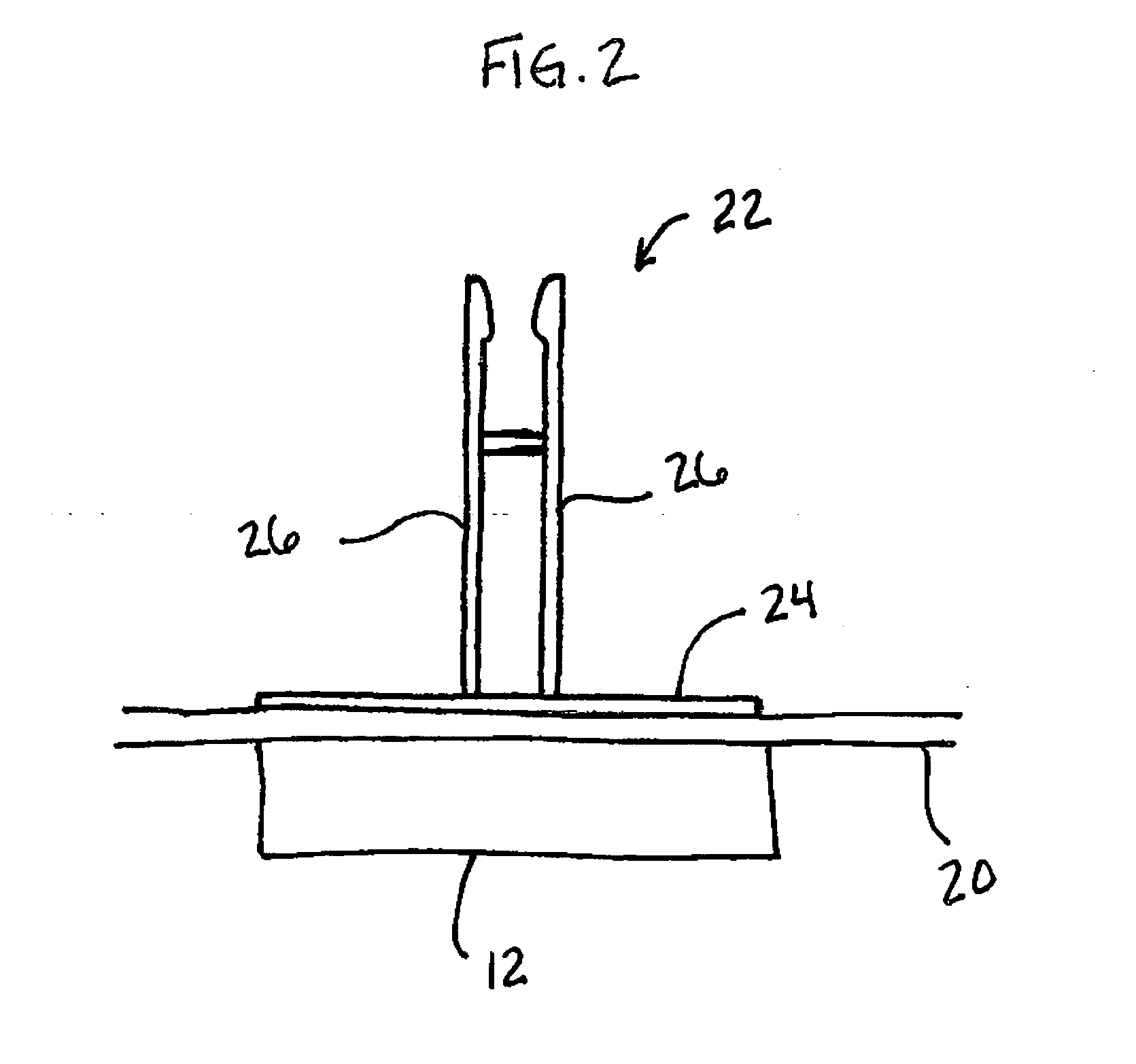
[0040] In the drawings, the thickness of the lines, layers, and regions may be exaggerated for clarity. It is to be noted that like numbers found throughout the figures denote like elements. The terms “top”, “bottom”, “side”, “upper”, “lower” and the like are used herein for the purpose of explanatio...


PUM

PropertyMeasurementUnit
densityaaaaaaaaaa
densityaaaaaaaaaa
Young's Modulusaaaaaaaaaa

Abstract

An acoustical absorbing membrane that may be used in removable panel finishing systems is provided. The acoustic membrane may be formed of any sound transmission loss material that possesses sound-absorbing or sound-deadening qualities. Examples of suitable materials include foil, a foil-faced asphalt material, elastomeric materials, composite laminates, a polymer film, a composite material formed of an organic bonding material and one or more types of reinforcement fibers, a cement board, a gypsum board, a gypsum/WUCS board, a dense WUCS mat, a film formed of a fiberglass reinforced resin, and/or any dense polymeric material. In at least one exemplary embodiment, the acoustic membrane may be a film formed of a loaded polymer or copolymer, such as a copolymer of ethylene-vinyl acetate loaded with barium or CaCO3. The acoustic membrane may have a density of approximately 1 lb/ft2-3 lbs/ft2 and preferably has a thickness from about 1/16-⅜ of an inch.

Description

TECHNICAL FIELD AND INDUSTRIAL APPLICABILITY OF THE INVENTION [0001] The present invention relates generally to removable panel finishing systems, and more particularly, to an acoustic partition that increases sound absorption in a removable panel finishing system for rooms such as may be found in single family homes or commercial buildings. BACKGROUND OF THE INVENTION [0002] Sound insulation materials are used in a variety of settings where it is desired to dampen noise from an external source. For example, sound insulation materials have been used in applications such as in appliances to reduce the sound emitted into the surrounding areas of a home, in automobiles to reduce mechanical sounds of the motor and road noise, and in office buildings to attenuate sound generated from the workplace, such as from telephone conversations or from the operation of office equipment. Acoustical insulation materials typically relies upon both sound absorption (i.e., the ability to absorb inciden...

Claims


Application Information

Patent Timeline
Patent Type & Authority Applications(United States)
IPC IPC(8): E04B1/82
CPCE04B2/7409E04B2/7457E04B2002/725
Inventor WEIR, CHARLES R.HERREMAN, KEVIN M.
Owner OWENS CORNING INTELLECTUAL CAPITAL LLC
Why Eureka
Try Eureka